Mold clamping device

The technology of a mold clamping device and a mold clamping mechanism, which is applied in the field of mold clamping devices, can solve problems such as the weight of the shaft support plate 106 and the weight increase of the mold clamping device 100, and achieve the effects of suppressing weight increase, realizing light weight, and reducing rigidity

Pending Publication Date: 2020-10-09
NISSEI PLASTIC IND CO LTD
View PDF6 Cites 0 Cited by
  • Summary
  • Abstract
  • Description
  • Claims
  • Application Information

AI Technical Summary

Problems solved by technology

[0019] When the thickness is increased, the shaft support plate 106 becomes h

Method used


Image

  • Mold clamping device
  • Mold clamping device
  • Mold clamping device

Examples


Embodiment Construction

[0049] Embodiments of the present invention will be described based on the drawings.

[0050] 【Example】

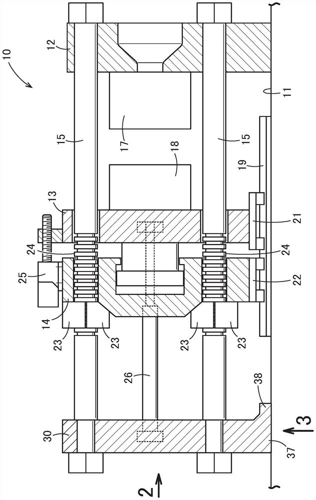
[0051] Such as figure 1 As shown, the mold clamping device 10 includes a base 11 , a fixed platen 12 , a movable platen 13 , a mold clamping mechanism 14 , a connecting rod 15 , and a shaft support plate 30 .

[0052] The fixed plate 12 is fixed on the base 11 .

[0053] The movable platen 13 is mounted on the base 11 so as to be movable.

[0054] The mold clamping mechanism 14 plays a role in pushing the movable platen 13 toward the fixed platen 12 .

[0055] The connecting rod 15 extends from the fixed plate 12 and passes through the movable plate 13 and the mold clamping mechanism 14 .

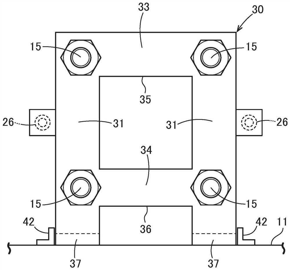
[0056] The shaft support plate 30 is placed on the base 11 and supports the front end of the connecting rod 15 .

[0057] The fixed plate 12 supports a fixed mold 17 .

[0058] The movable die 13 supports a movable die 18 .

[0059] Preferably, the track 19 is laid on the foundat...


PUM


Abstract

The invention provides a mold clamping device which can prevent bending of a connecting rod. The mold clamping device (10) includes a base (11), a stationary platen (12), a movable platen (13), a moldclamping mechanism (14), a tie bar (15), and a half nut (23). This mold clamping device (10) further includes a shaft supporting plate (30) supporting a tip of the tie bar (15). This shaft supportingplate (30) is fixed to the tip of the tie bar (15), and is mounted on the base (11) so as to be freely movable.

Description

technical field [0001] The invention relates to a mold clamping device for mold clamping. Background technique [0002] Injection molding device is mainly composed of injection device and clamping device. The resin material is injected into the mold by the injection device. At this time, it is necessary that the mold does not open due to injection pressure. Therefore, the mold is clamped by the mold clamping device. [0003] Conventionally, as a mold clamping device, various methods are known (for example, refer to Patent Document 1 ( figure 1 )). [0004] Patent Document 1 will be described based on the following figures. [0005] Figure 8 It is a figure explaining the basic structure of the prior art, and the mold clamping apparatus 100 is equipped with: the base 101; the fixed disk 102 fixed to this base 101; Plate 103; Clamping cylinder 104 that pushes the movable plate 103 to the fixed plate 102; Extending from the fixed plate 102 and penetrating the connecting ...

Claims


Application Information

Patent Timeline
IPC IPC(8): B29C45/66B29C45/68
CPCB29C45/6728B29C45/66B29C45/68B29C45/64B29C33/24B29C45/6707B29C2045/688
Inventor 依田穂积星野智大久保浩男村田敦户泽启一
Owner NISSEI PLASTIC IND CO LTD
Why Eureka
Try Eureka