
LED automobile lamp installation limiting device

A technology of LED car lights and limit devices, which is applied in the direction of motor vehicles, transportation and packaging, etc., can solve the problems of manual fixing, achieve the effects of accurate installation, prevent the position of car lights from shifting, and facilitate installation

Active Publication Date: 2020-10-09
惠安县品创工业设计有限公司
View PDF9 Cites 0 Cited by
  • Summary
  • Abstract
  • Description
  • Claims
  • Application Information

AI Technical Summary

Problems solved by technology

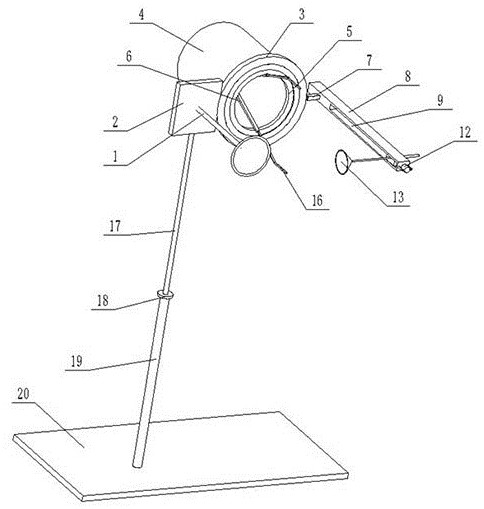
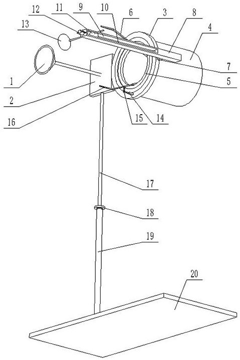
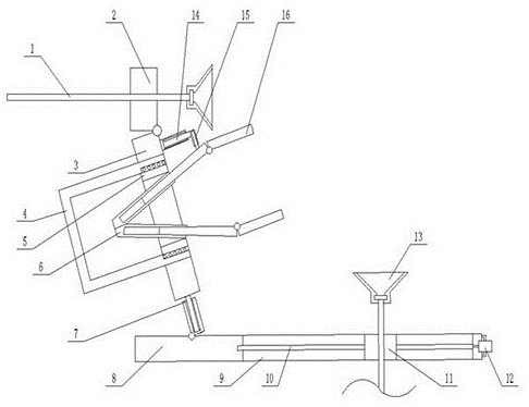
[0003] In view of the above problems, the present invention provides an installation limit device for LED automobile lamps, which clamps the lamps by driving two clamp rods through the hydraulic cylinder, and then aligns them with the installation position, and then fixes the rubber suction cup on the fixing device I on the automobile. At the front end, finally connect the rubber suction cup on the fixing device Ⅱ to the side of the car, and turn the drum to move the light to the installation groove on the car, which solves the problem of manual fixing for the installation of the light and makes the installation more accurate; start The motor drives the horizontal screw to rotate. Since the slider is fixed by the fixing device Ⅱ, the connecting rod moves to the right when the horizontal screw rotates, thereby driving the connecting ring Ⅰ to move and tilting the drum with the lamp, which is convenient for different angles of the lamp. When disassembling, manually remove the fixing device Ⅰ and fixing device Ⅱ, which can be quickly disassembled, saving disassembly time and making the equipment convenient for next use

Method used


Image

  • LED automobile lamp installation limiting device
  • LED automobile lamp installation limiting device
  • LED automobile lamp installation limiting device

Examples


Embodiment Construction

[0022] The technical solutions of the present invention will be further specifically described below through the embodiments and in conjunction with the accompanying drawings. In the following description, many specific details are set forth in order to fully understand the present invention, but the present invention can be implemented in many other ways different from those described here, and those skilled in the art can do similar Modifications, and therefore the present invention is not limited to the specific examples disclosed below.

[0023] In the description of the present invention, it should be noted that the orientation or positional relationship indicated by the terms "up", "down", "front", "rear", "left", "right" etc. are based on the Orientation or positional relationship, or the orientation or positional relationship that the inventive product is usually placed in use, is only for the convenience of describing the present invention and simplifying the descript...


PUM


Abstract

The invention provides an LED automobile lamp installation limiting device which comprises a fixing device I, a rotary drum, a hydraulic cylinder and a fixing device II. Two clamping rods are driven by the hydraulic cylinder to move to clamp the vehicle lamp, then the installation position is aligned; a rubber suction cup on the fixing device I is fixed to the front end of the automobile, finallya rubber suction cup on the fixing device II is fixedly connected with the side face of the automobile, the rotary drum is rotated to move the automobile lamp into an installation groove in the automobile, the problem that the automobile lamp needs to be manually fixed is solved, and installation is more accurate. A motor is started to drive a transverse screw rod to rotate, and a sliding block is fixed by the fixing device II, so that a connecting rod moves rightwards when the transverse screw rod rotates, a connecting ring I is driven to move to incline the rotary drum with the vehicle lamp, and vehicle lamps at different angles are convenient to mount; and during disassembly, the fixing device I and the fixing device II are manually taken down, so that the disassembly time is saved through quick disassembly, and the equipment is convenient to use next time.

Description

technical field [0001] The invention relates to the technical field of automobile equipment, in particular to an installation limiting device for an LED automobile lamp. Background technique [0002] With the development of society and the advancement of science and technology, the automobile industry has gradually been improved. The lamp of a car is one of the most important parts in a car. Due to the large energy consumption of the previous halogen headlights, the loss is also very fast, so Replacing with LED car lights can reduce energy consumption, save energy and protect the environment. When installing LED car lights, the existing methods of bolt connection and snap-fit ​​are used to fix the car lights on the front of the car body. Manually fixing the car lights is very tiring, so Fixing devices are required for the installation of car lights, but the traditional fixing devices are not only complicated to install, but also cannot be freely adjusted to install lights at...

Claims


Application Information

Patent Timeline
Patent Type & Authority Applications(China)
IPC IPC(8): B62D65/16
CPCB62D65/16
Inventor 张金新王华辉
Owner 惠安县品创工业设计有限公司
Learn More