A twisted-blade blower or vacuum pump

A blower, vacuum pump technology, applied in the direction of pumps, pump components, mechanical equipment, etc., can solve the problem of low work efficiency, achieve the effect of improving work efficiency, ensuring permeability and filtering effect, and stabilizing the filtering effect

Active Publication Date: 2022-08-02
浙江珂勒曦动力设备股份有限公司
View PDF0 Cites 0 Cited by
  • Summary
  • Abstract
  • Description
  • Claims
  • Application Information

AI Technical Summary

Problems solved by technology

However, when the driving screw and the driven screw are working, the gas can only be sucked and exhausted through the narrow gap between the driving screw and the driven screw, and the work efficiency is low, which needs to be improved.

Method used


Image

  • A twisted-blade blower or vacuum pump
  • A twisted-blade blower or vacuum pump
  • A twisted-blade blower or vacuum pump

Examples


Embodiment 1

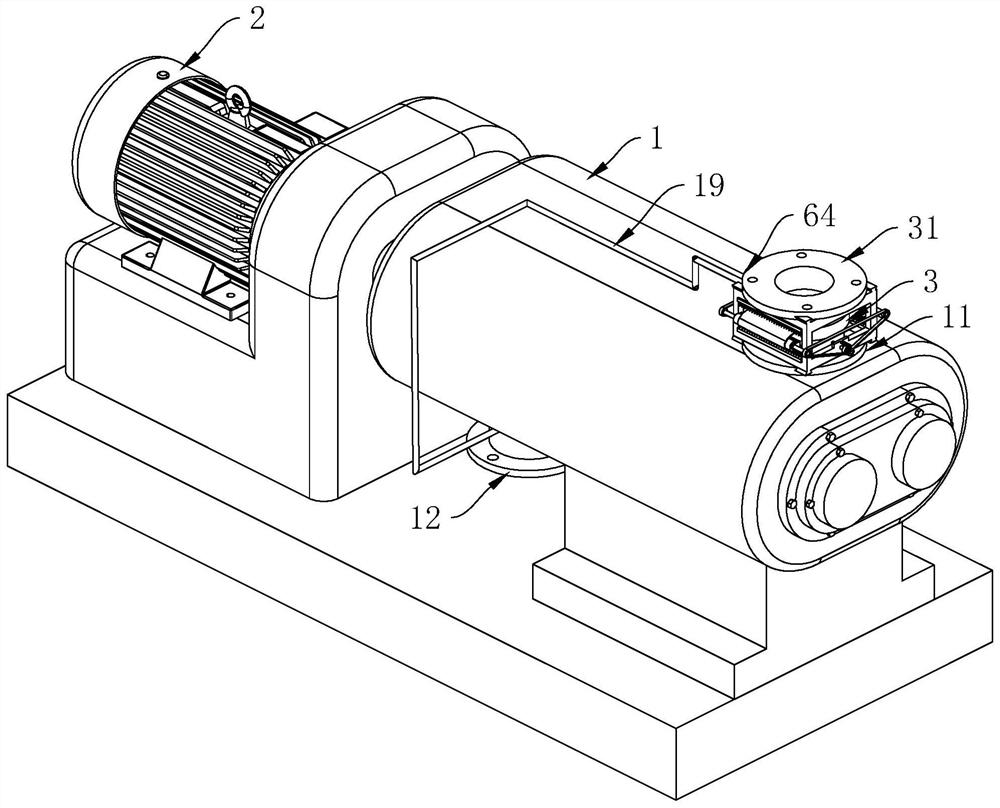
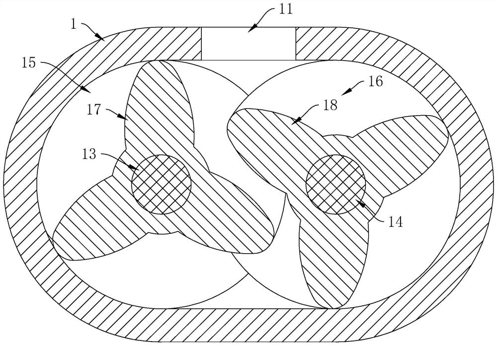
[0036] Example 1: as figure 1 , figure 2 As shown, a twist-blade blower or vacuum pump includes a body 1 and a motor 2. The upper end of the body 1 is provided with an air inlet 11 and the lower end is provided with an exhaust port 12. A driving shaft 13 and a driven shaft 14 are connected horizontally in the body 1, and the outer walls of the driving shaft 13 and the driven shaft 14 are respectively provided with a driving twisting blade 15 and a driven twisting blade 16.

[0037] like figure 1 , figure 2 As shown, the driving twisted vane 15 and the driven twisted vane 16 respectively include three evenly distributed driving vanes 17 and driven vanes 18, and the driving vanes 17 and the driven vanes 18 are twisted from the front end to the rear end toward the side approaching each other , and form a twist angle of 30-120°.

[0038]When the above-mentioned blower is working, the motor 2 is used to control the synchronous high-speed rotation of the driving shaft 13 and t...

Embodiment 2

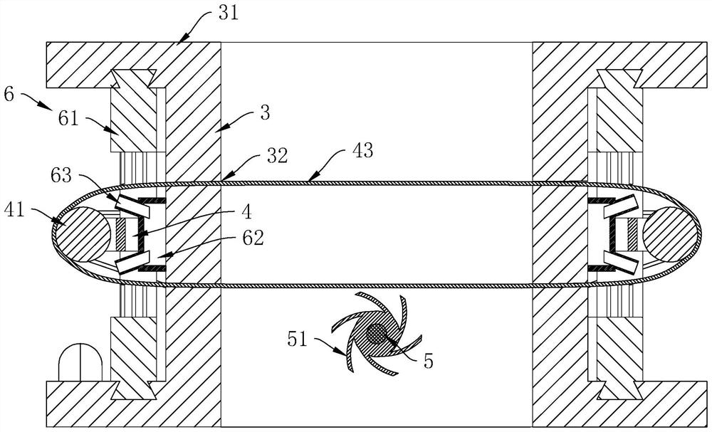
[0057] Example 2: as image 3 , Figure 4 As shown, the blower in this embodiment can also be used as a vacuum pump. When used as a vacuum pump, the air inlet pipe 3 is covered by a sealing cover, so that a sealed chamber is formed between the air inlet pipe 3 and the sealing cover.


PUM


Abstract

The invention discloses a twist-blade blower or vacuum pump, which relates to the field of air transmission equipment. The driven twisted vanes, the active twisted vanes and the driven twisted vanes respectively include three evenly distributed drive vanes and driven vanes, and the drive vanes and driven vanes twist from the front end to the rear end toward the side close to each other, and form 30 ‑120° twist angle. The invention has the following advantages and effects: by utilizing the cooperation of the three driving blades and the driven blades, a space for gas to enter is formed, and at the same time, when the driving shaft and the driven shaft rotate once, the suction and exhaust are carried out six times each, and the blower is realized. efficient work, improve work efficiency, and achieve the effect of energy saving.

Description

technical field [0001] The invention relates to the field of air conveying equipment, in particular to a twisted-blade blower or a vacuum pump. Background technique [0002] The screw blower uses the same pair of screw rotors to mesh and rotate. During the process from suction, compression to exhaust, it is an ideal pneumatic conveying air source for chemical, food and other industries. Since the screw blower has the same structure as the screw vacuum pump, the screw blower can also be used as a screw vacuum pump, in which the working end of the screw blower is at the exhaust port, and the working end of the screw vacuum pump is at the air inlet. [0003] When the traditional screw blower is in use, the synchronous high-speed reverse rotation of the active screw and the driven screw is used to realize the continuous suction and exhaust of the gas. However, when the driving screw and the driven screw are working, the gas can only be inhaled and exhausted through the narrow g...

Claims


Application Information

Patent Timeline
Patent Type & Authority Patents(China)
IPC IPC(8): F04C18/16F04C25/02F04C29/00
CPCF04C18/16F04C25/02F04C29/0092
Inventor 许祖近刘永胜
Owner 浙江珂勒曦动力设备股份有限公司
Why Eureka
Try Eureka