
A kind of cable drawing structure and cable drawing method

A cable and wire drawing technology, which is applied in the field of cable wire drawing structure and wire drawing, can solve the problems of poor design of guide rollers or guide devices, poor applicability, time-consuming and labor-intensive problems, etc.

Active Publication Date: 2022-05-20
青海鑫邦线缆有限公司
View PDF12 Cites 0 Cited by
  • Summary
  • Abstract
  • Description
  • Claims
  • Application Information

AI Technical Summary

Problems solved by technology

[0008] (1) The design of the guide roller or the guide device is not good, and the effect of maintaining the tension of the cable drawing is low, which easily affects the normal operation and drawing accuracy of the cable drawing;
[0009] (2) Second, the wire drawing mechanism is simple in structure and poor in applicability. Usually, it can only support a single specification of cable drawing. If it is necessary to adapt to cables of different specifications, it is often necessary to replace the drawing roller substantially. Time-consuming;

Method used


Image

  • A kind of cable drawing structure and cable drawing method
  • A kind of cable drawing structure and cable drawing method
  • A kind of cable drawing structure and cable drawing method

Examples


Embodiment 1

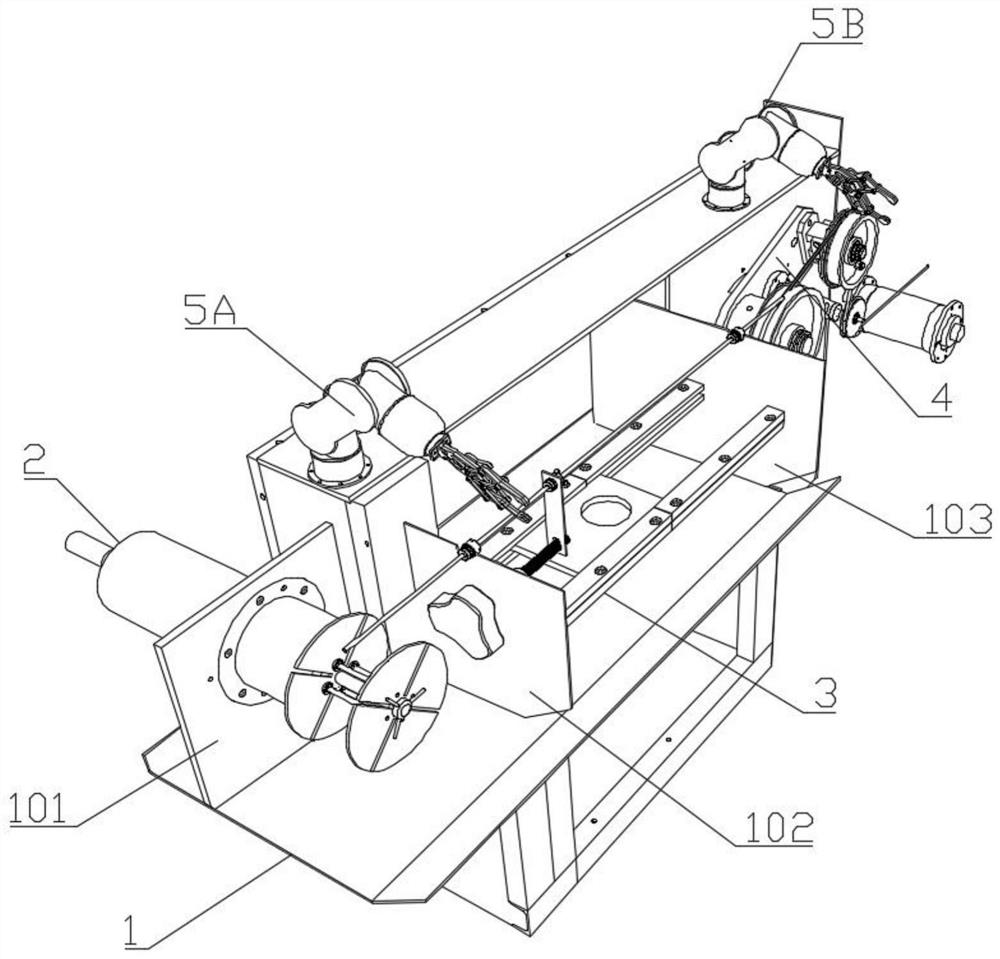
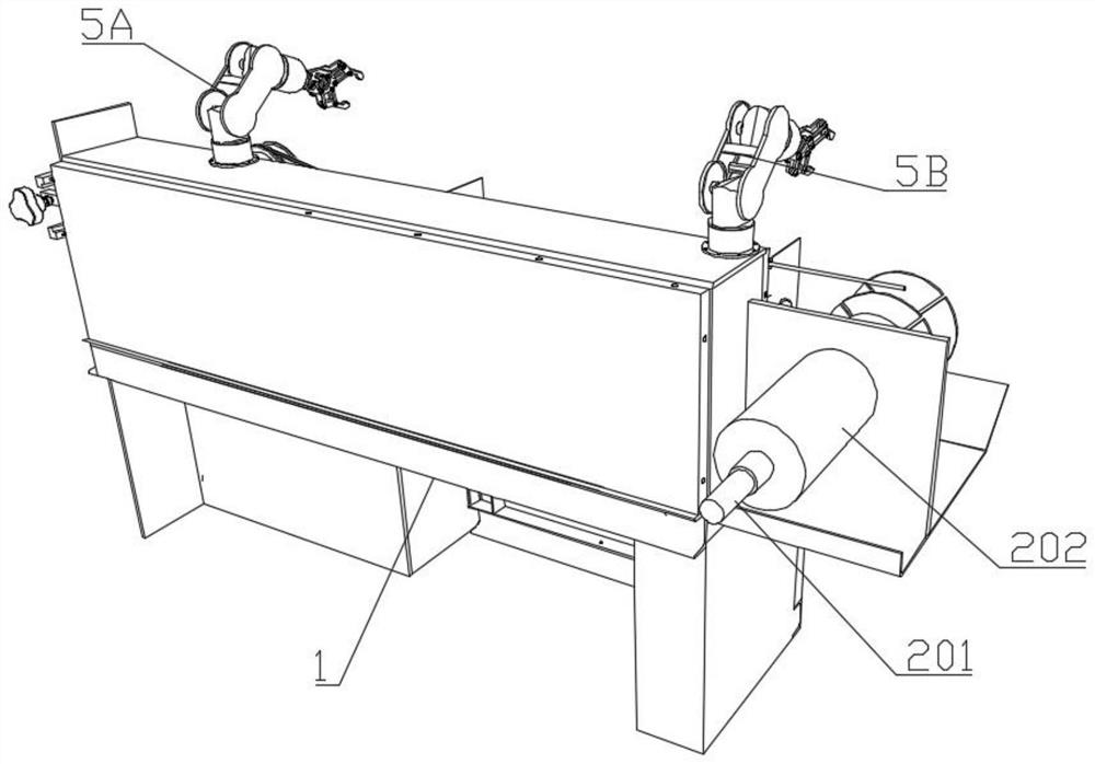
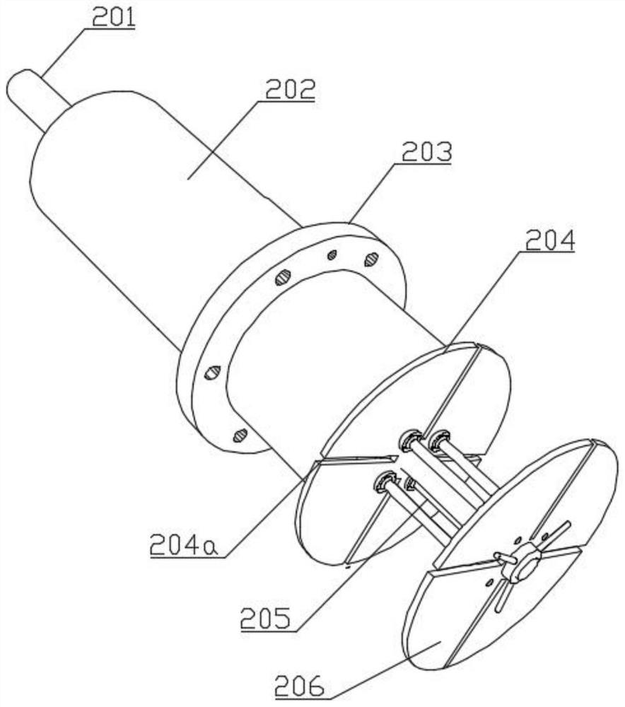
[0043] Such as Figure 1-4 As shown, a cable drawing structure includes a wire-drawing box, and a wire-drawing assembly 2 and a wire-drawing assembly 4 are arranged on the wire-drawing box in sequence according to the direction of cable travel; the wire-drawing assembly 2 includes a pay-off wheel and a single To the wire fixing device, the pay-off wheel is arranged at the head end of the wire feeding box, and the axis of the pay-off wheel is perpendicular to the wire drawing direction of the cable. The one-way wire fixing device includes two one-way wire fixing devices, which are respectively the first one-way wire fixing device 207 And the second one-way wire fixing device 208, the first one-way wire fixing device 207 and the second one-way wire fixing device 208 are all arranged on the right side of the pay-off wheel, and the first one-way wire fixing device 207 and the second one-way wire fixing device 207 The wire fixing devices 208 are all fixed on the wire payout box, an...

Embodiment 2

[0051] Such as Figure 1-7 As shown, a cable drawing structure includes a wire-drawing box, and a wire-drawing assembly 2 and a wire-drawing assembly 4 are arranged on the wire-drawing box in sequence according to the direction of cable travel; the wire-drawing assembly 2 includes a pay-off wheel and a single To the wire fixing device, the pay-off wheel is arranged at the head end of the wire feeding box, and the axis of the pay-off wheel is perpendicular to the wire drawing direction of the cable. The one-way wire fixing device includes two one-way wire fixing devices, which are respectively the first one-way wire fixing device 207 And the second one-way wire fixing device 208, the first one-way wire fixing device 207 and the second one-way wire fixing device 208 are all arranged on the right side of the pay-off wheel, and the first one-way wire fixing device 207 and the second one-way wire fixing device 207 The wire fixing devices 208 are all fixed on the wire payout box, an...


PUM


Abstract

The invention relates to the technical field of cable processing, in particular to a cable drawing structure, which includes a wire-drawing box, on which a wire-drawing assembly and a wire-drawing assembly are arranged; The wire fixing device, the pay-off wheel is arranged at the head end of the pay-off box, and the axis of the pay-off wheel is perpendicular to the drawing direction of the cable, and the one-way wire fixing device includes a first one-way wire fixing device and a second one-way wire fixing device The wire fixing device, the first one-way wire fixing device and the second one-way wire fixing device respectively have a first wire-through hole and a second wire-through hole, and the cables pass through the first wire-through hole and the second wire-through hole in turn, Finally, through the wire drawing assembly; the wire drawing assembly includes a wire drawing wheel and a take-up roller, the drawing wheel is rotatably connected to the wire delivery box through a rotating shaft, and the take-up roller is installed on the wire delivery box. The present invention provides a wire drawing accuracy, A cable drawing structure that can adapt to different specifications and can complete good cable winding, and a cable drawing method of the cable drawing structure is also provided.

Description

technical field [0001] The invention relates to the technical field of cable processing, in particular to a cable drawing structure and a cable drawing method. Background technique [0002] With the advancement of wire and cable processing technology, the conductors of power cables have begun to develop into a shaped wire stranded structure. The shaped wire stranded conductor has the characteristics of a small outer diameter layer and a smooth surface. And the application of shaped wire stranded conductors in power cables also has the advantages of reducing cable breakdown rate, smaller conductor outer diameter under the same cross-section, reducing the use of insulating materials and sheath materials, and improving conductor compression coefficient (0.98). [0003] Comparing the copper stranded conductor with shaped wire to the round compact conductor, under the same resistance, the plastic variation of copper is small, and the molecular structure distribution in the copper...

Claims


Application Information

Patent Timeline
Patent Type & Authority Patents(China)
IPC IPC(8): B21C1/02B21C47/34H01B13/00
CPCB21C1/02B21C47/34H01B13/0006H01B13/0036
Inventor 赵阳孙建营谢夏青赵帅奇冯茹霞
Owner 青海鑫邦线缆有限公司
Learn More