Adjustable slitting equipment special for model manufacturing

A model manufacturing and adjustable technology, applied in the direction of manufacturing tools, metal processing equipment, large fixed members, etc., can solve the problems of inconvenient work, reduced work efficiency, heavy model weight, etc., and achieve the effect of stable cutting process and easy retraction

Inactive Publication Date: 2020-10-13
刘斌兴
View PDF6 Cites 2 Cited by
  • Summary
  • Abstract
  • Description
  • Claims
  • Application Information

AI Technical Summary

Problems solved by technology

[0002] Through subjective consciousness with the help of physical or virtual representation, it constitutes an object that expresses the purpose of objectively explaining the form and structure (objects are not equal to objects, not limited to entities and virtual, not limited to plane and three-dimensional), and the form of the model can be divided into entities Models (conceptual physical objects with volume and weight) and virtual models (figures composed of electronic data through digital representations and other practical representations). At present, some models use steel or other metal materials as the basis for manufacturing. Compared with Because the plastic material is tougher and has better drop resistance, but the metal steel frame is heavy and inconvenient to move during production, so it needs to be cut by cutting equipment
[0003] When the slitting equipment is in use, due to the long length of the fixed part of the model, when it is necessary to cut a model that is not located in the fixture, in order to improve the stability of the cutting process, it is usually necessary to adjust the position of the model. However, some models are heavy, and re-adjusting the clamping after clamping and fixing not only reduces work efficiency, but also requires more labor and brings inconvenience to the work.

Method used


Image

  • Adjustable slitting equipment special for model manufacturing
  • Adjustable slitting equipment special for model manufacturing
  • Adjustable slitting equipment special for model manufacturing

Examples


Embodiment 1

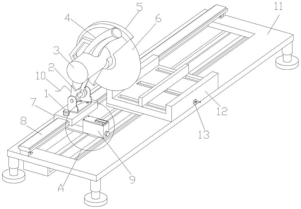
[0030] see figure 1 and figure 2 , the present invention provides a special adjustable cutting device for model manufacturing through improvement, including a fixed screw 1, a support frame 2, a power cord 10 and a base 11, and a screw hole provided at the rear end of the fixed screw 1 and the top surface of the sliding frame 7 The inner thread connection, the support frame 2 is hinged on the inner top of the sliding frame 7, and the top surface of the support frame 2 is fastened with the motor 3, the front end surface and the top surface of the motor 3 are respectively locked with the protective cover 5 and the handle 4, and the front end of the motor 3 outputs The shaft passes through the rear end of the protective cover 5 and is fixedly connected to the inner ring of the cutting piece 6. The sliding frame 7 is slidably installed on the guide rail 8 locked on the left end of the top surface of the base 11. The power cord 10 is connected to the power input end of the motor 3...

Embodiment 2

[0034] The present invention provides an adjustable slitting equipment for model manufacturing through improvement. The inner end surface of the protective cover 5 covers the outer middle and upper end of the cutting piece 6, which is convenient for protecting the cutting piece 6 and preventing the workers from touching the cutting piece. 6, the handle 4 is an arc-shaped rod that tapers from bottom to top.

[0035] The present invention provides a special adjustable cutting equipment for model making through improvement, and its working principle is as follows;

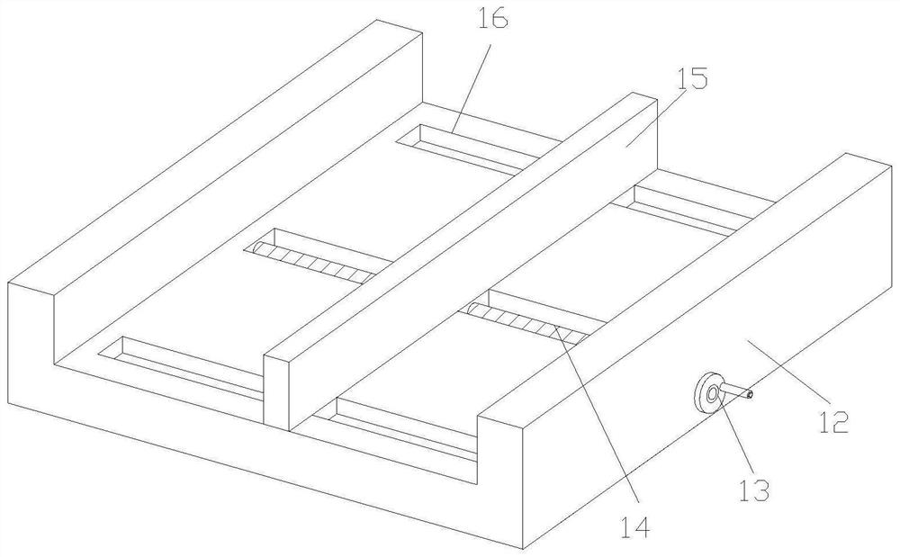
[0036] First, first connect the power cord 10 to the external controller, then place the model that needs to be cut between the front end face of the splint 15 and the inner front end face of the U-shaped fixed plate 12, and then turn the turntable 13 to drive the screw rod 14 Rotate, so that the splint 15 is driven by the screw 14 to move to the left to clamp the model;

[0037] Second, start the motor 3 by the exte...


PUM


Abstract

The invention discloses adjustable slitting equipment special for model manufacturing. The adjustable slitting equipment special for model manufacturing comprises a fixing screw, a supporting frame, apower line and a base. An auxiliary supporting mechanism is arranged at the top end of the inner side of the base. A shell is driven to move by moving an L-shaped connecting plate, and the rotating plate is then rotated to drive a lead screw to rotate to enable a U-shaped block to be driven by the lead screw to move rightwards; meanwhile, the U-shaped block drives a fixed column to move rightwards so as to push a curved plate to rotate upwards, and the curved plate drives a round rod to rotate upwards when rotating upwards; and meanwhile, the round rod pushes a U-shaped plate to vertically move upwards, so that a connecting plate, a supporting plate and an extension supporting plate are pushed by the U-shaped plate to move upwards and be attached to the bottom of a model, models not located in a fixture are assistantly supported, and the mold cutting process is more stable.

Description

technical field [0001] The invention relates to the related field of slitting equipment, in particular to an adjustable slitting equipment dedicated to model manufacturing. Background technique [0002] Through subjective consciousness with the help of physical or virtual representation, it constitutes an object that expresses the purpose of objectively explaining the form and structure (objects are not equal to objects, not limited to entities and virtual, not limited to plane and three-dimensional), and the form of the model can be divided into entities Models (conceptual physical objects with volume and weight) and virtual models (figures composed of electronic data through digital representations and other practical representations). At present, some models use steel or other metal materials as the basis for manufacturing. Compared with Because the plastic material is tougher and has better drop resistance, but the metal steel frame is heavy and inconvenient to move duri...

Claims


Application Information

Patent Timeline
Patent Type & Authority Applications(China)
IPC IPC(8): B23Q1/72B23Q1/76B23Q1/25B23Q3/06
CPCB23Q1/25B23Q1/72B23Q1/76B23Q1/766B23Q3/06B23Q3/062
Inventor 刘斌兴
Owner 刘斌兴
Why Eureka
Try Eureka