

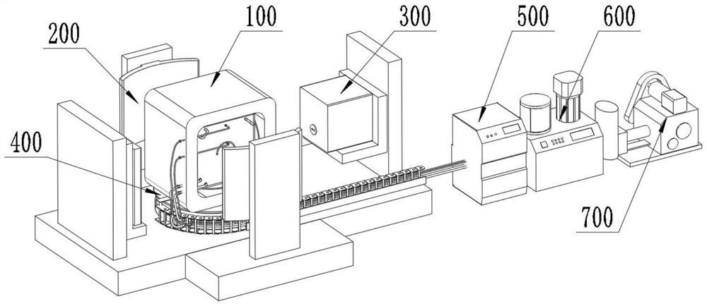
A visual test system for simulating the process of grouting and seepage in fractured rock mass
A test system and seepage technology, applied in the control/regulation system, permeability/surface area analysis, instruments, etc., can solve the problems such as the inability to realize the visual detection of rock mass grouting, save money, manpower and material resources, convenient operation, and test low cost effect
- Summary
- Abstract
- Description
- Claims
- Application Information
AI Technical Summary
Problems solved by technology
Method used
Image

Examples
Embodiment Construction
[0042] The preferred embodiments of the present invention are described below with reference to the accompanying drawings. Those skilled in the art should understand that these embodiments are only used to explain the technical principles of the present invention, and are not intended to limit the protection scope of the present invention.
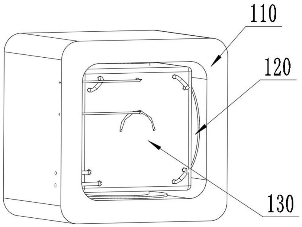
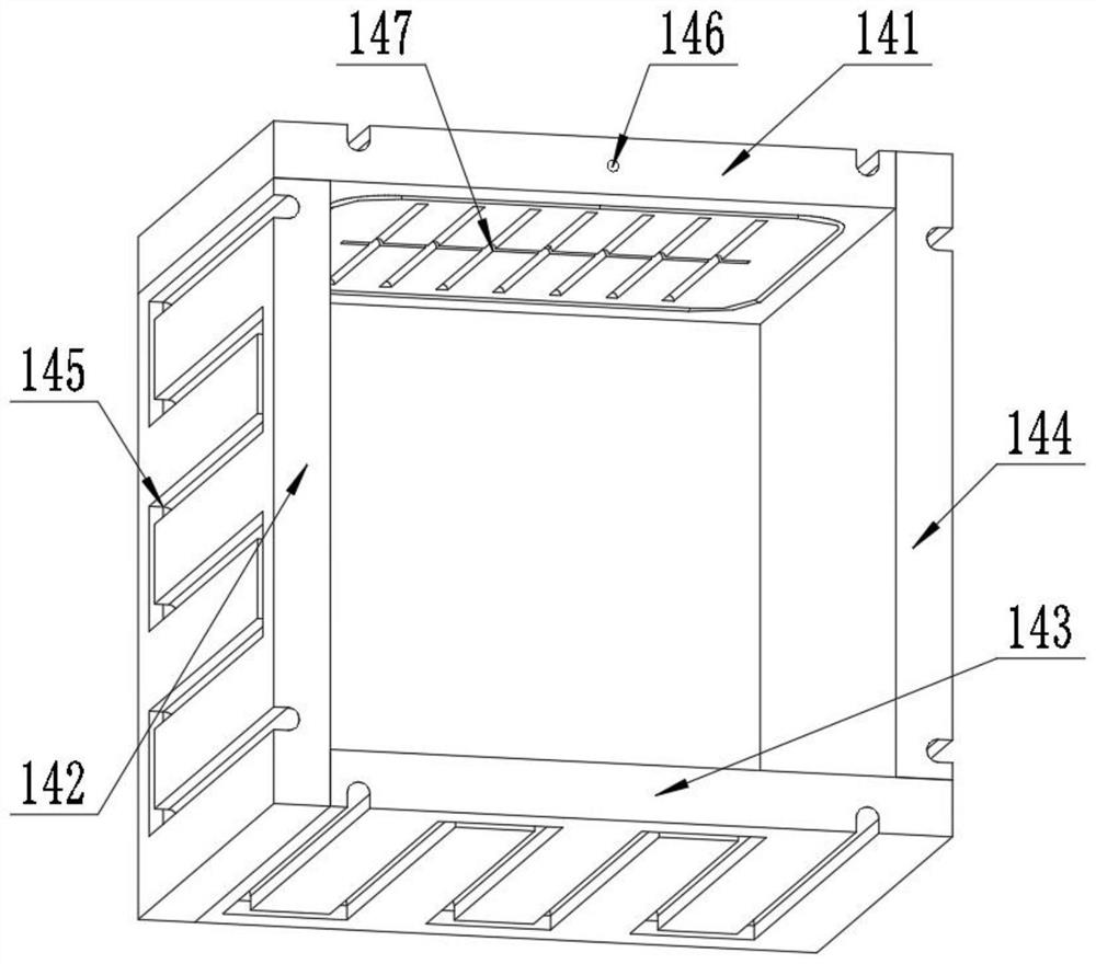
[0043] The invention provides a visual test system for simulating the grouting and seepage process of rock mass with cracks, including an experimental cabin system, a grouting system, a temperature control system, a water permeability control system, a rotating bearing system and a detection scanning system, wherein the grouting system The system is used to control the grouting of rock mass specimens and simulate the reinforcement of the surrounding rock of the tunnel; the temperature control system includes a temperature control pump and a temperature control pipeline, and the temperature control pump simulates the rock mass specimen throug...
PUM
 Abstract
Description
Claims
Application Information