Visual monitoring system used for electric power operation maintenance

A technology of operation maintenance and monitoring system, applied in the field of electric power, can solve the problems of easy pollution, loss, casualty and economy of installation, and achieve the effects of avoiding power interference, precise steering setting, and accurate steering

Active Publication Date: 2019-09-10
STATE GRID HEBEI ELECTRIC POWER CO LTD +1
View PDF14 Cites 4 Cited by
  • Summary
  • Abstract
  • Description
  • Claims
  • Application Information

AI Technical Summary

Problems solved by technology

[0003] When some electricity places need to be monitored and visually managed, the current, voltage and other power parameter acquisition devices and image acquisition devices are generally installed on site to obtain real-time conditions on site, but in some occasions that are inconvenient to install or easy to deface The image acquisition device is prone to failure, and the on-site situation cannot be known; at t

Method used


Image

  • Visual monitoring system used for electric power operation maintenance
  • Visual monitoring system used for electric power operation maintenance
  • Visual monitoring system used for electric power operation maintenance

Examples


Embodiment 1

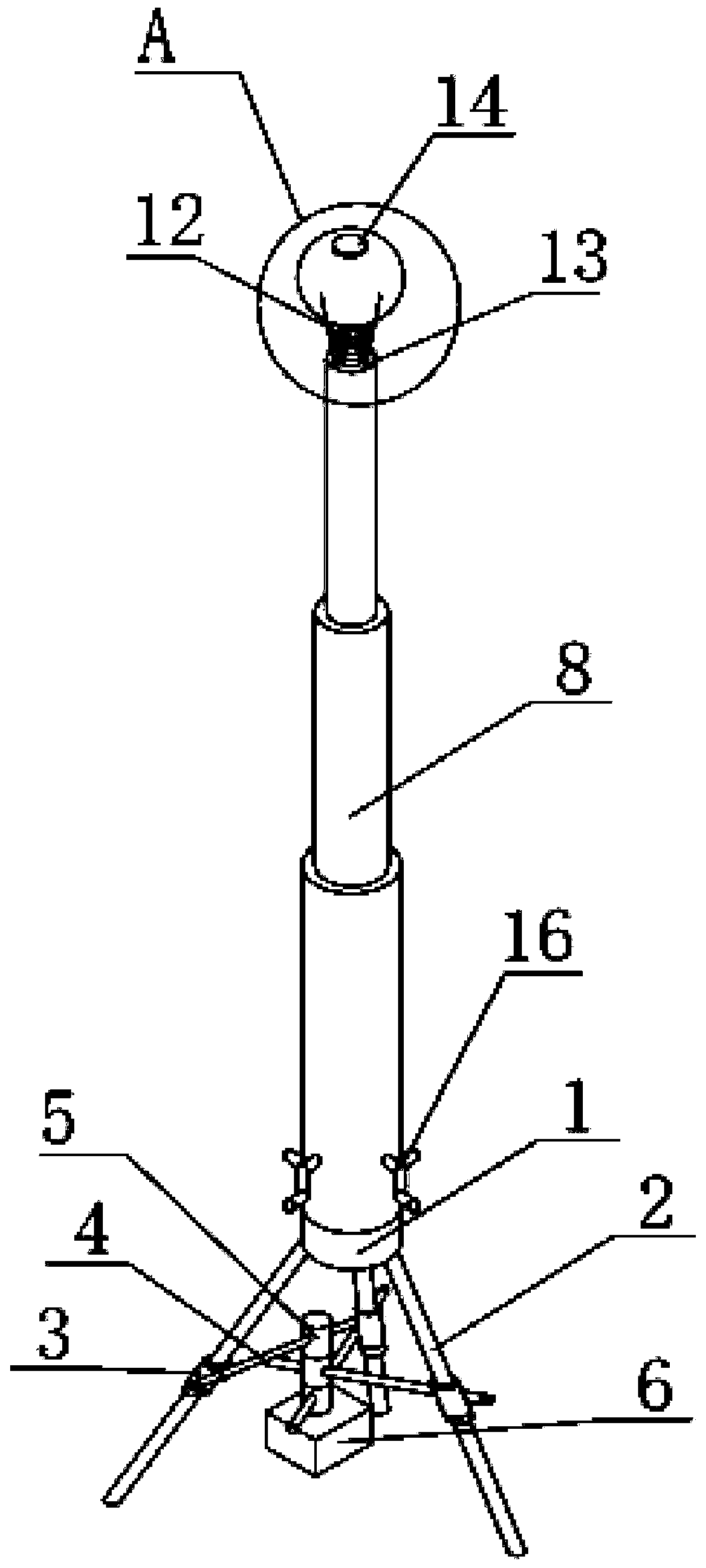
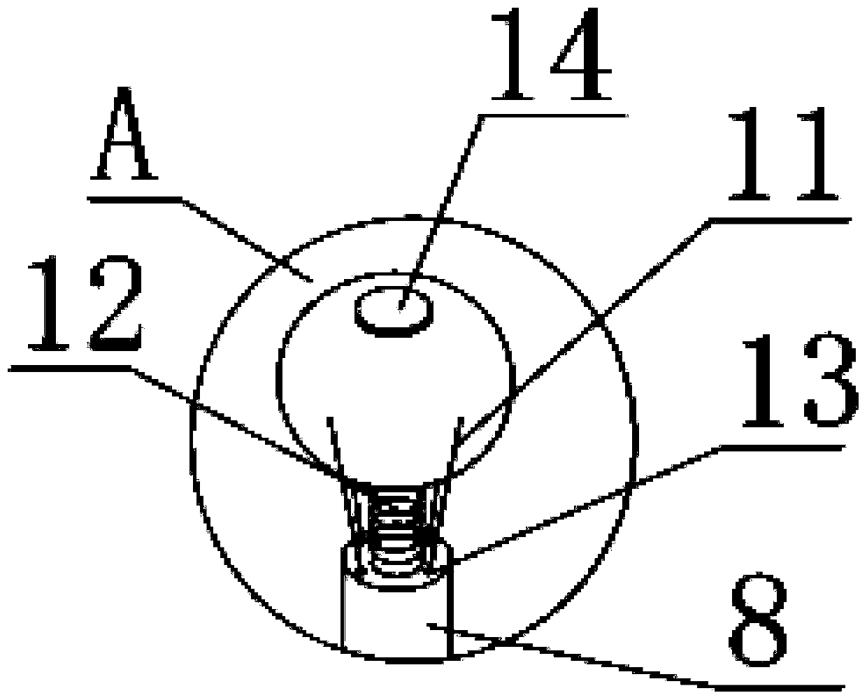
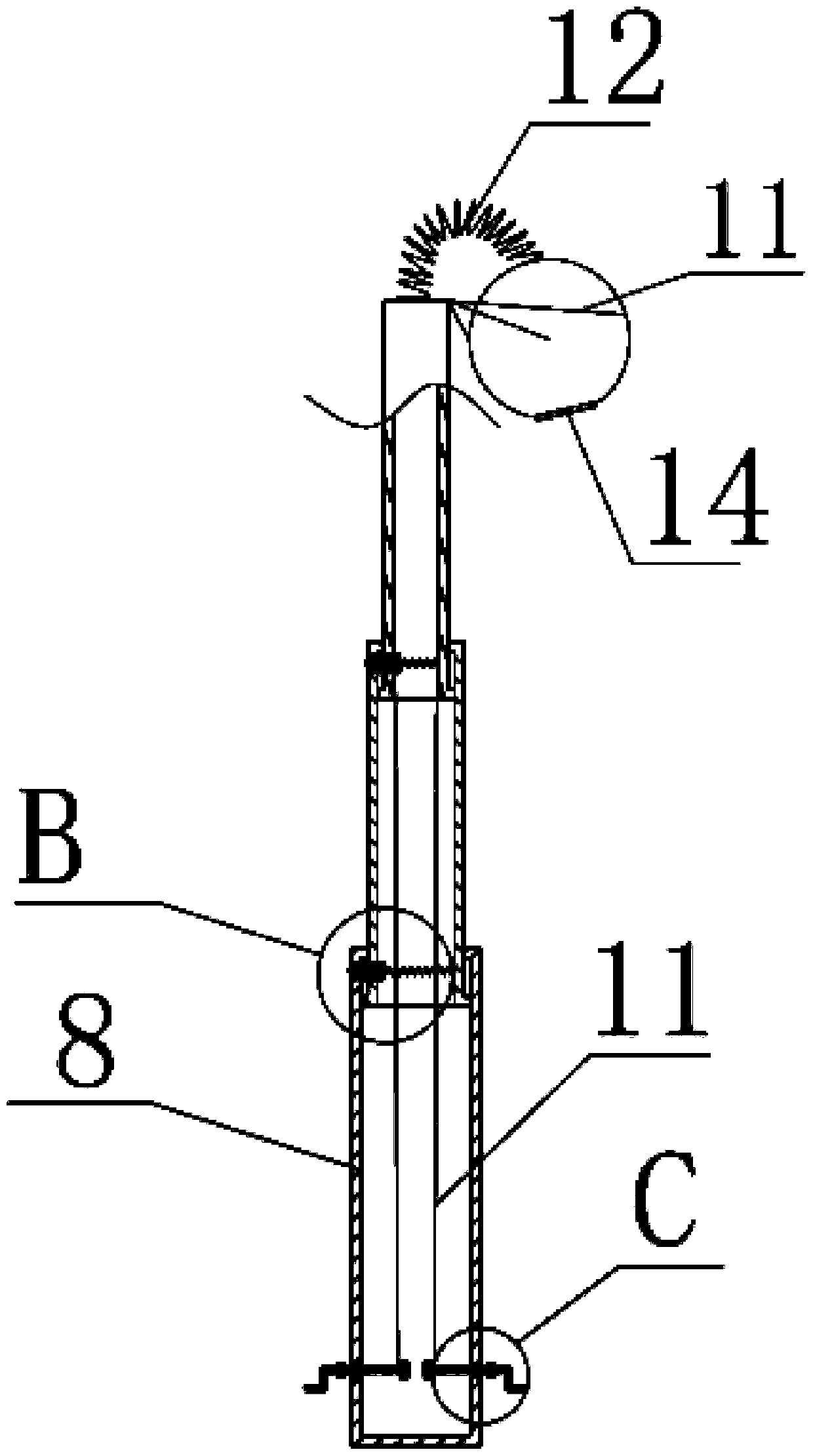
[0023] Example 1, such as Figure 1 to Figure 5 As shown, a power supply, a controller, and a positioning module are installed in the electrical box 1 of the portable image acquisition device, and the power supply supplies power to the power consumption modules such as the controller and the positioning module. During operation and maintenance work, the general server sends instructions to the operator, and the instruction is sent to the operator by means of wireless communication, such as SMS, WeChat, and the position of the portable image acquisition device is determined by the positioning module, and the collected image is displayed on the display screen. Image and position information, in order to facilitate the on-site operators to adjust the position of the camera, a screen is also installed on the electrical box for real-time display of the images collected by the camera 14; then, the operators go to the site of power operation and maintenance to work, the site condition...

Embodiment 2

[0025] Example 2, when the ground of the workplace is a slope, the common solution is to add weight to the base or to connect it to the ground. However, the weighted base cannot realize the portable function, and the way to connect to the ground is not only cumbersome to operate, but also can be used on the concrete floor. Therefore, none of the existing methods can well solve the problem of stable placement encountered by portable acquisition devices;

[0026] After many times of scheme improvement and design, the three claws 2 are respectively provided with sliding sleeves 3 with sliding rods 4, and the three sliding rods 4 form a cross connection structure by means of an intermediate hinge unit. Sliding cylinder 5, each sliding cylinder 5 is inserted with a sliding rod 4, and the bottom of the lowermost sliding cylinder 5 is equipped with a counterweight 6; three sliding rods 4 can slide freely along the sliding sleeve 3, and the three sliding cylinders 5 Articulation rotat...


PUM


Abstract

The invention relates to a visible monitoring system used for electric power operation maintenance. The visible monitoring system comprises a collection unit positioned on the spot, a master server positioned in a master control room and a display screen, wherein the collection unit is connected with the master server through a wireless signal; the master server is connected with the display screen; the collection unit comprises a portable image collection unit, and the portable image collection unit comprises a base, a telescopic rod, a steering mechanism and a camera which are arranged frombottom to top in sequence; the base comprises an electrical box and three claws at the bottom of the electrical box, a sliding sleeve with a sliding rod is arranged on each claw respectively; a crossed connecting structure is formed by the three sliding rods by means of intermediate hinged units; each intermediate hinged unit comprises three sliding barrels which are vertically hinged in sequence;each sliding rod is inserted in the corresponding sliding barrel; and a balancing weight is mounted at the bottom of the sliding barrel at the lowest end. The monitoring system realizes the operationmaintenance of electrical equipment site by means of a portable image collection device, and visual monitoring for various electrical operation maintenance occasions is realized.

Description

technical field [0001] The invention belongs to the field of electric power technology, and in particular relates to a visual monitoring system for electric power operation and maintenance. Background technique [0002] One of the main responsibilities of the power dispatching department is to ensure the safe and stable operation of the power grid. It often monitors the power equipment within the jurisdiction to ensure that the power equipment can operate normally, thereby avoiding affecting the safety and stability of the power grid. [0003] When some electricity places need to be monitored and visually managed, the current, voltage and other power parameter acquisition devices and image acquisition devices are generally installed on site to obtain real-time conditions on site, but in some occasions that are inconvenient to install or easy to deface The image acquisition device is prone to failure, and the on-site situation cannot be known; at the same time, in some occasi...

Claims


Application Information

Patent Timeline
IPC IPC(8): H02J13/00H04N7/18F16M11/04F16M11/12F16M11/18F16M11/28F16M11/38
CPCH02J13/0013H04N7/18F16M11/04F16M11/121F16M11/18F16M11/28F16M11/38H02J13/00001Y04S10/40
Inventor 张晶宋丹张肖杰王兆辉杨超刘云龙张伟尹静王强于瑞丰
Owner STATE GRID HEBEI ELECTRIC POWER CO LTD
Why Eureka
Try Eureka