Optical lens and imaging device

An optical lens and lens technology, applied in optics, optical components, instruments, etc., can solve the problems of ordinary lens optical back focus shift, small-sized lens resolution aberration, affecting normal use, etc., and achieve high screen brightness and clear light Large aperture and good image quality

Active Publication Date: 2020-10-13
NINGBO SUNNY AUTOMOTIVE OPTECH
View PDF4 Cites 3 Cited by
  • Summary
  • Abstract
  • Description
  • Claims
  • Application Information

AI Technical Summary

Problems solved by technology

[0003] Ordinary small-sized lenses have poor resolution, and due to volume limitations, it is difficult to enlarge the aperture, so they cannot meet the normal use in low-light environments
[0004] In addition, in some harsh environments, for example, vehicle-mounted lenses need to be able to be used in low-temperature environments with severe ice and snow and high-temperature environments with direct sunlight. Due to the large temperature difference, the optical back focus of ordinary lenses will shift, affecting normal operation. use
In order to suppress the deviation of the optical back focus of the lens as the temperature changes, the traditional method is to use an expensive optical glass lens with a small thermal expansion coefficient, but this will greatly increase the cost of the lens, which is not conducive to mass production and use.

Method used


Image

  • Optical lens and imaging device
  • Optical lens and imaging device
  • Optical lens and imaging device

Examples


Embodiment 1

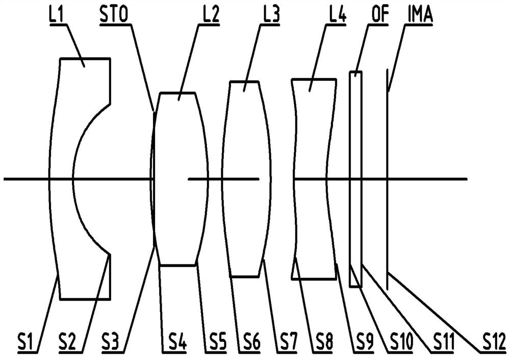
[0071] The following reference figure 1 The optical lens according to Embodiment 1 of the present application is described. figure 1 A schematic structural diagram of an optical lens according to Embodiment 1 of the present application is shown.

[0072] Such as figure 1 As shown, the optical lens includes a first lens L1, a second lens L2, a third lens L3, and a fourth lens L4 in order from the object side to the imaging side along the optical axis.

[0073] The first lens L1 is a meniscus lens with negative refractive power, and its object side surface S1 is a convex surface, and the image side surface S2 is a concave surface.

[0074] The second lens L2 is a double-convex lens with positive refractive power, and the object side surface S4 and the image side surface S5 are both convex.

[0075] The third lens L3 is a double-convex lens with positive refractive power, and the object side surface S6 and the image side surface S7 are both convex.

[0076] The fourth lens L4 is a meniscus...

Embodiment 2

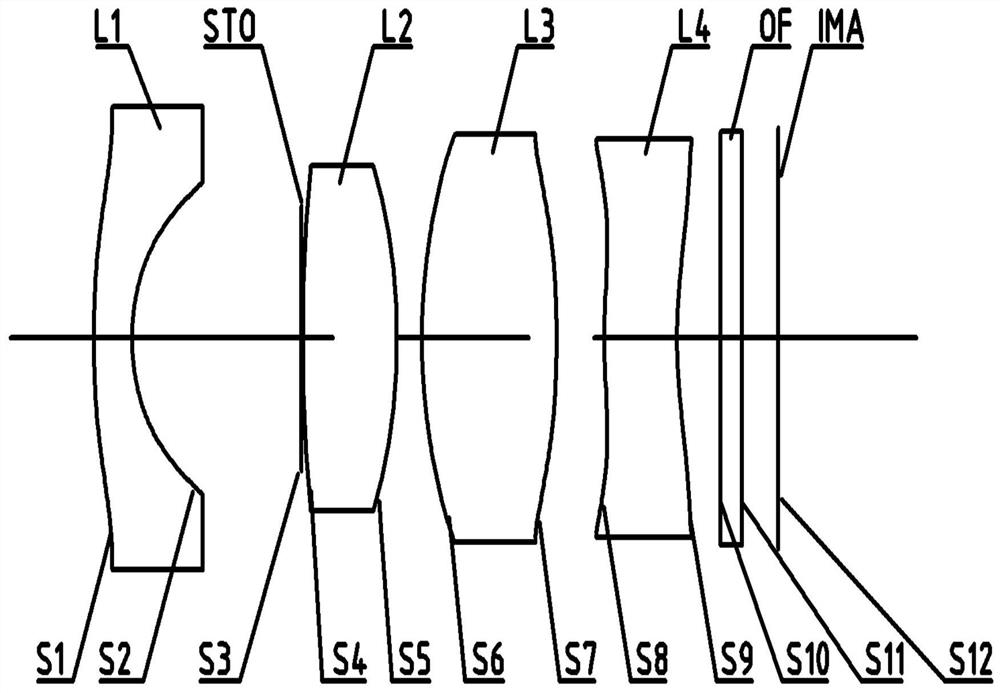
[0094] The following reference figure 2 The optical lens according to Embodiment 2 of the present application is described. In this embodiment and the following embodiments, for the sake of brevity, some descriptions similar to those in Embodiment 1 will be omitted. figure 2 A schematic structural diagram of an optical lens according to Embodiment 2 of the present application is shown.

[0095] Such as figure 2 As shown, the optical lens includes a first lens L1, a second lens L2, a third lens L3, and a fourth lens L4 in order from the object side to the imaging side along the optical axis.

[0096] The first lens L1 is a meniscus lens with negative refractive power, and its object side surface S1 is a convex surface, and the image side surface S2 is a concave surface.

[0097] The second lens L2 is a double-convex lens with positive refractive power, and the object side surface S4 and the image side surface S5 are both convex.

[0098] The third lens L3 is a double-convex lens wit...

Embodiment 3

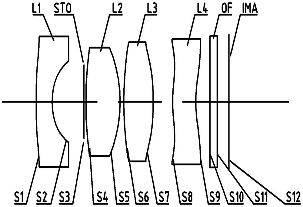
[0112] The following reference image 3 The optical lens according to Embodiment 3 of the present application is described. In this embodiment and the following embodiments, for the sake of brevity, some descriptions similar to those in Embodiment 1 will be omitted. image 3 A schematic structural diagram of an optical lens according to Embodiment 3 of the present application is shown.

[0113] Such as image 3 As shown, the optical lens includes a first lens L1, a second lens L2, a third lens L3, and a fourth lens L4 in order from the object side to the imaging side along the optical axis.

[0114] The first lens L1 is a meniscus lens with negative refractive power, and its object side surface S1 is a convex surface, and the image side surface S2 is a concave surface.

[0115] The second lens L2 is a double-convex lens with positive refractive power, and the object side surface S4 and the image side surface S5 are both convex.

[0116] The third lens L3 is a double-convex lens with p...


PUM


Abstract

An optical lens and an imaging device including the same are disclosed. The optical lens can sequentially comprise a first lens, a second lens, a third lens and a fourth lens from the object side to the image side along the optical axis. The first lens can have negative focal power, the object side surface of the first lens is a convex surface, and the image side surface of the first lens is a concave surface; the second lens can have positive focal power, and the object side surface and the image side surface of the second lens are convex surfaces; the third lens can have positive focal power, and the object side surface and the image side surface of the third lens are convex surfaces; the fourth lens can have negative focal power, the object side face of the fourth lens is a convex face,the image side face of the fourth lens is a concave face, and the object side face or the image side face comprises at least one inflection point. According to the optical lens provided by the invention, at least one of the beneficial effects of good imaging quality, good thermal compensation, large field angle, large clear aperture, high picture brightness, miniaturization and the like can be achieved.

Description

Technical field [0001] The present application relates to an optical lens and an imaging device including the optical lens. More specifically, the present application relates to an optical lens and an imaging device including four lenses. Background technique [0002] With the development of science and technology and the improvement of application requirements, optical lenses have been widely used in many fields, and the requirements for the resolution of the lens are getting higher and higher; at the same time as the integration of equipment increases, the requirements for the lens size are getting smaller and smaller. . [0003] Ordinary small-size lenses have poor resolution and are limited by their size. It is difficult to enlarge the clear aperture, so they cannot meet normal use in low-illuminance environments. [0004] In addition, in some harsh environments, for example, car lenses need to be able to be used in low-temperature environments with severe ice and snow and high-...

Claims


Application Information

Patent Timeline
Patent Type & Authority Applications(China)
IPC IPC(8): G02B13/00G02B13/18
CPCG02B13/004
Inventor 周召涛王东方
Owner NINGBO SUNNY AUTOMOTIVE OPTECH
Why Eureka
Try Eureka