Lamp box mounting structure for exhibition hall design

A technology for installing structures and light boxes, which is applied to display devices, mechanical equipment, instruments, etc., can solve the problems of large wall damage, troublesome disassembly, unfavorable protection of exhibition hall walls, etc., and achieve the effect of improving practicability and avoiding wall damage

Inactive Publication Date: 2020-10-13
上海逊达建筑设计工程有限公司
View PDF13 Cites 1 Cited by
  • Summary
  • Abstract
  • Description
  • Claims
  • Application Information

AI Technical Summary

Problems solved by technology

[0003] The installation of the light box in the existing exhibition hall is directly fixed on the wall by screws or bolts. However, when the light box needs to be disassembled for maintenance and replacement, it is not only troublesome to disassemble, but also needs to be screwed in again during installation. Or bolts, repeated drilling on the wall will cause great damage to the wall, and the protection of the exhibition hall wall will not be used.

Method used


Image

  • Lamp box mounting structure for exhibition hall design
  • Lamp box mounting structure for exhibition hall design
  • Lamp box mounting structure for exhibition hall design

Examples


Embodiment 1

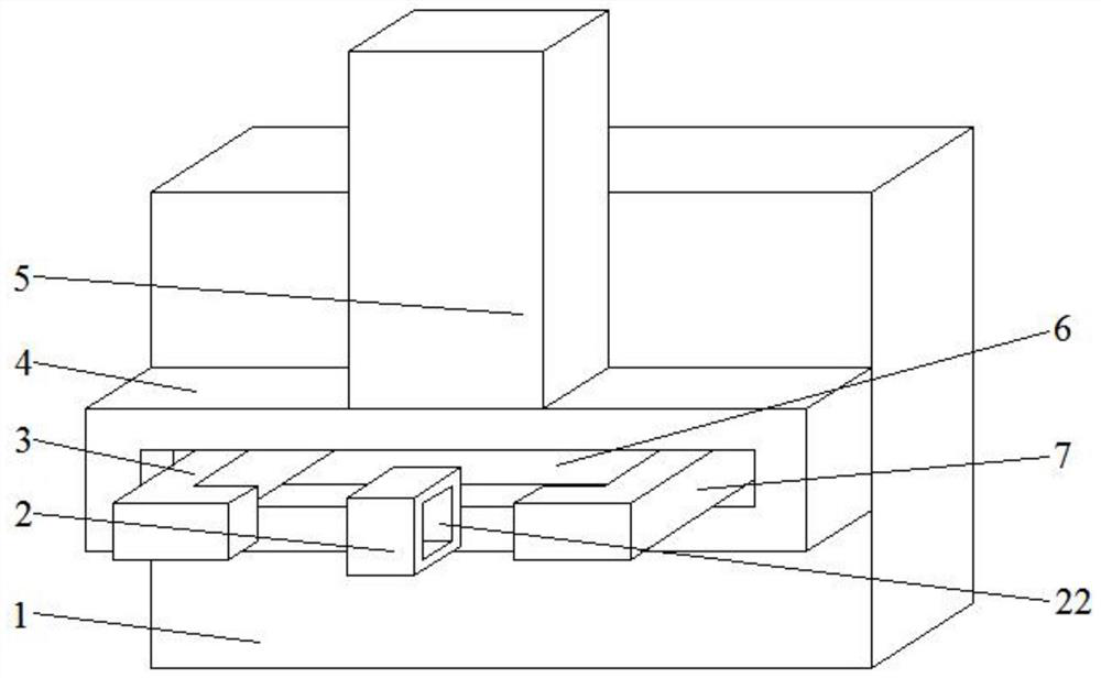
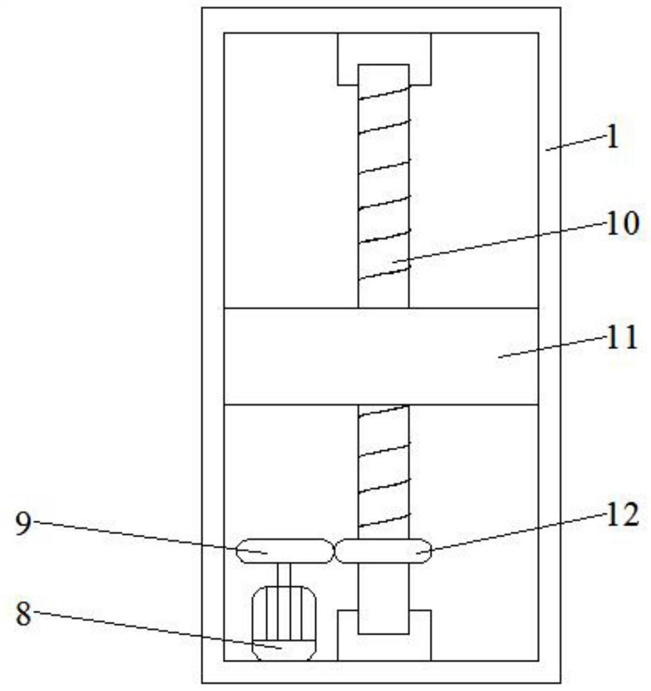
[0024] Reference Figure 1-3 , A light box installation structure for exhibition hall design, comprising a light box 1, a box body 4 and a fixing block 2. The box body 4 is slidably connected to one side of the light box 1, and the box body 4 is arranged parallel to the light box 1, and the top of the box body 4 is welded with The box body 5 is provided with a lifting mechanism for lifting the light box 1 inside the box body 5, and the two ends of the box body 4 away from the light box 1 are slidably connected with a first L-shaped rod 3 and a second L-shaped rod 7. The L-shaped rod 3 and the second L-shaped rod 7 are arranged symmetrically, and the lateral sides of the first L-shaped rod 3 and the second L-shaped rod 7 are arranged parallel to the box body 4, and the fixed block 2 is located at the first L-shaped rod 3 and the second L-shaped rod 3 Between the opposite ends of the horizontal side of the L-shaped rod 7 and the side of the fixed block 2 close to the first L-shap...

Embodiment 2

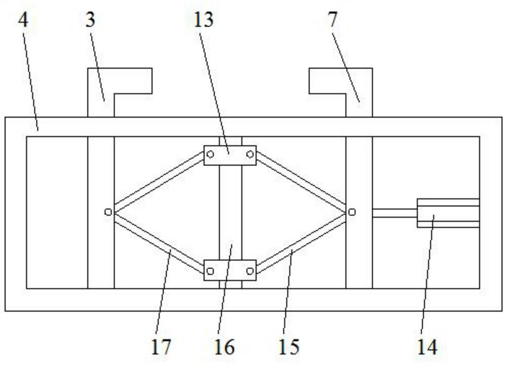
[0028] Reference Figure 4 The difference between this embodiment and Embodiment 1 is that the moving mechanism includes a first pulley 18, a second pulley 21 and a belt 20, and the first pulley 18, the second pulley 21 and the belt 20 are all rotatably connected to the inside of the box body 4. , The belt 20 is sleeved on the first pulley 18 and the second pulley 21, and the first pulley 18 and the second pulley 21 are arranged in parallel, the upper horizontal edge of the belt 20 passes through the vertical edge of the first L-shaped rod 3 and is bonded to the first Inside the vertical side of the L-shaped bar 3, and the lower horizontal side of the belt 20 passes through the vertical side of the first L-shaped bar 3 and is slidably connected to the inside of the vertical side of the first L-shaped bar 3, and the upper horizontal side of the belt 20 passes through the second L-shaped bar 7 The vertical edge is slidably connected to the inside of the vertical edge of the second...


PUM


Abstract

The invention discloses a lamp box mounting structure for exhibition hall design. The lamp box mounting structure comprises a lamp box, a case body and a fixing block. The case body is slidably connected to one side of the lamp box. A box body is welded to the top of the case body. A lifting mechanism used for lifting the lamp box is arranged in the box body. The two ends of the side, away from the lamp box, of the case body are slidably connected with a first L-shaped rod and a second L-shaped rod correspondingly. The fixing block is located between the two opposite ends of the transverse edge of the first L-shaped rod and the transverse edge of the second L-shaped rod. A square through hole is formed in the side, close to the first L-shaped rod, of the fixing block. The transverse edgesof the first L-shaped rod and the second L-shaped rod are both connected into the square through hole in a sliding mode. A strip-shaped groove is formed in the side, away from the lamp box, of the case body. The vertical edges of the first L-shaped rod and the second L-shaped rod penetrate through the strip-shaped groove and are slidably connected into the case body. A moving mechanism used for moving the first L-shaped rod and the second L-shaped rod is arranged in the case body. The practicability of the lamp box is improved.

Description

Technical field [0001] The invention relates to the technical field of installation of light boxes in exhibition halls, in particular to a light box installation structure for exhibition hall design. Background technique [0002] The light box is a viewing light box for perspective X-ray photos. Light boxes generally use light films, preferably PC boards. Because of their beautiful appearance and strong advertising effect, light boxes are widely used by a large number of people, including exhibition halls. The exhibition hall needs to install it before using the light box. [0003] The existing exhibition halls install light boxes directly on the wall with screws or bolts. However, when the light box needs to be disassembled, maintained and replaced, it is not only troublesome to disassemble, but also needs to be screwed in again during installation. Or bolts, repeated drilling holes on the wall can cause great damage to the wall, so the protection of the wall of the exhibition ha...

Claims


Application Information

Patent Timeline
Patent Type & Authority Applications(China)
IPC IPC(8): G09F13/04F16M13/02
CPCF16M13/02G09F13/04G09F13/0413
Inventor 邓定金
Owner 上海逊达建筑设计工程有限公司
Why Eureka
Try Eureka