Active heat dissipation type new energy battery mounting base

An active heat dissipation, new energy technology, applied in secondary batteries, battery pack components, circuits, etc., can solve the problems of reduced service life, loose connection screws, inconvenient installation and removal of batteries, etc., to prevent shaking and disassembly. And the effect of easy installation

Inactive Publication Date: 2020-10-13
邹新亮
View PDF0 Cites 4 Cited by
  • Summary
  • Abstract
  • Description
  • Claims
  • Application Information

AI Technical Summary

Problems solved by technology

[0003] 1. The installation of the existing new energy battery is generally to open the installation shell, and then install the new energy battery into it through the connecting screw, which leads to the extremely inconvenient installation and removal of the battery in the actual use process , and during the working process of the battery, the connection screws may become loose after a long time;
[0004] 2. The current new energy batteries generally do not have an active cooling function, and the battery will emit a lot of heat during the working process. The heat dissipation is actually part of the power loss, and the battery has been working in a high temperature environment for a long time , the service life will be greatly reduced, so how to control the working temperature of the battery in a timely and efficient manner is a problem we need to consider

Method used


Image

  • Active heat dissipation type new energy battery mounting base
  • Active heat dissipation type new energy battery mounting base

Examples


Embodiment Construction

[0016] The following will clearly and completely describe the technical solutions in the embodiments of the present invention with reference to the accompanying drawings in the embodiments of the present invention. Obviously, the described embodiments are only some, not all, embodiments of the present invention.

[0017] In describing the present invention, it should be understood that the terms "upper", "lower", "front", "rear", "left", "right", "top", "bottom", "inner", " The orientation or positional relationship indicated by "outside", etc. is based on the orientation or positional relationship shown in the drawings, and is only for the convenience of describing the present invention and simplifying the description, rather than indicating or implying that the referred device or element must have a specific orientation, so as to Specific orientation configurations and operations, therefore, are not to be construed as limitations on the invention.

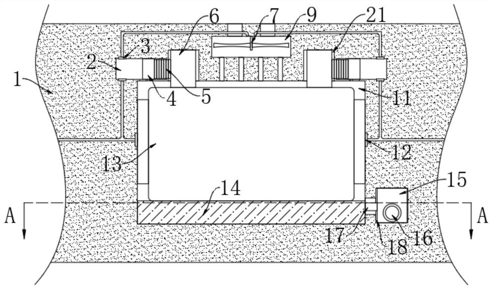
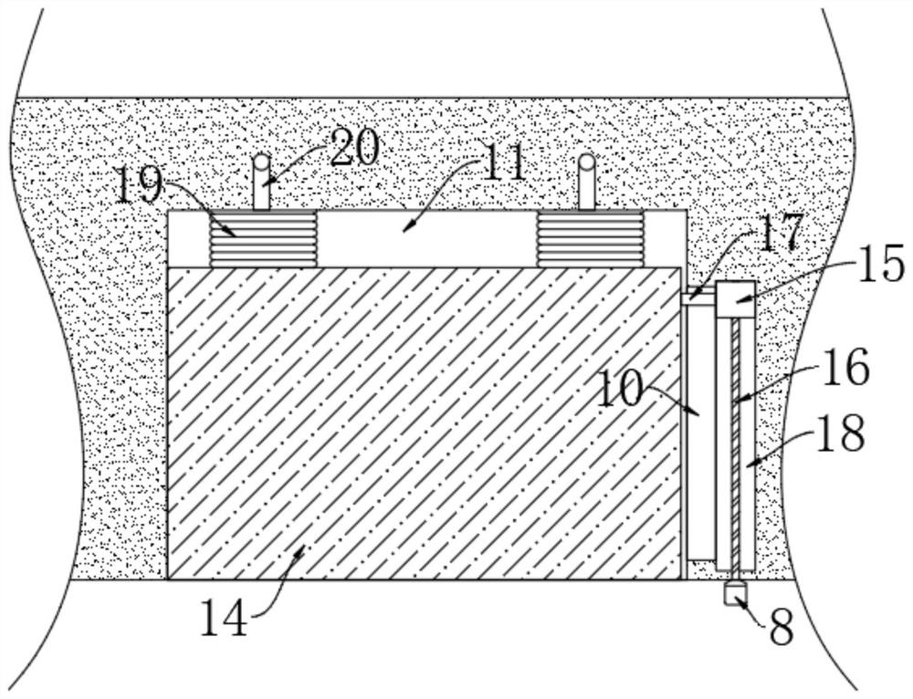
[0018] refer to Figure ...


PUM


Abstract

The invention discloses an active heat dissipation type new energy battery mounting base comprising a mounting shell and a battery mounting mechanism. A mounting groove is formed in the front side ofthe mounting shell; two limiting grooves are formed in the upper end of the mounting groove, two transverse cavities are symmetrically formed in the mounting shell, the two transverse cavities communicate with the two limiting grooves correspondingly, a heat dissipation cavity is formed in the mounting shell, the heat dissipation cavity is located between the two transverse cavities, the heat dissipation cavity is located above the mounting groove, and a vertical cavity is formed in the right side of the mounting groove. The battery mounting mechanism comprises a mounting plate arranged at thebottom in the mounting groove, the mounting plate is slidably connected with the inner wall of the mounting groove, and a battery body is mounted at the upper end of the mounting plate. According tothe mounting base, the battery can be disassembled and assembled very conveniently; meanwhile, through the design of a first expansion air bag, mounting is very firm, the working temperature of the battery can be efficiently controlled in time, and the service life of the battery is guaranteed.

Description

technical field [0001] The invention relates to the field of new energy, in particular to an active heat dissipation type new energy battery mounting base. Background technique [0002] New energy, also known as unconventional energy, refers to various forms of energy other than traditional energy, generally renewable energy developed and utilized on the basis of new technologies, and new energy batteries are an energy storage component for new energy utilization. New energy batteries are widely used in various energy vehicles, but when installing new energy batteries, there are still the following problems: [0003] 1. The installation of the existing new energy battery is generally to open the installation shell, and then install the new energy battery into it through the connecting screw, which leads to the extremely inconvenient installation and removal of the battery in the actual use process , and during the working process of the battery, the connection screws may be...

Claims


Application Information

Patent Timeline
Patent Type & Authority Applications(China)
IPC IPC(8): H01M2/10H01M2/20H01M10/613H01M10/625H01M10/635H01M10/6563
CPCH01M10/613H01M10/625H01M10/635H01M10/6563Y02E60/10
Inventor 邹新亮陈柯柯
Owner 邹新亮
Why Eureka
Try Eureka