Medicine spraying device for respiratory medicine department

A technology of respiratory internal medicine and rotating device, which is applied in the direction of medicine equipment and other medical equipment, etc. It can solve the problems of insufficient light in the mouth, uneven medicine spraying, and difficulty in finding the affected area for medical staff, so as to achieve comprehensive and uniform medicine spraying Effect

Active Publication Date: 2020-10-16
许云霞
View PDF19 Cites 10 Cited by
  • Summary
  • Abstract
  • Description
  • Claims
  • Application Information

AI Technical Summary

Benefits of technology

This patented technology allows for easy access by injecting liquids directly onto areas where they may cause harm or disease. It also includes features like twisting off medication containers with screw threads, pulling them towards one side while moving their plunger handles, pushing the contents downwardly, turning the container around, and controllably adjusting its direction before use. Additionally, there has been developed a mechanism called a dispenser system that uses pressure instead of force to deliver fluids effectively without causing any damage from excessive pressurization. Overall, these technical improvements make the process easier and safer than current methods such as syringe injection.

Problems solved by technology

The technical problem addressed by this patented technology relates to finding effective ways to treat breathing related conditions such as sinusitis without causing uncomfortable symptoms like dryness sensations during swallowings due to medicines being applied through existing devices used for these purposes.

Method used


Image

  • Medicine spraying device for respiratory medicine department
  • Medicine spraying device for respiratory medicine department
  • Medicine spraying device for respiratory medicine department

Examples


Embodiment 1

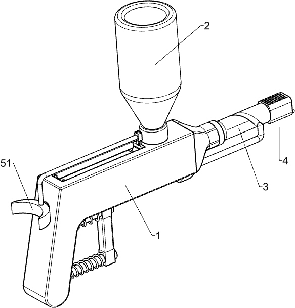
[0021] see figure 1 and figure 2 , a spraying device for respiratory internal medicine, including a housing 1, a rotary joint 3, a spraying head 4, a pushing device 5 and a rotating device 6, the top right side of the housing 1 is provided with a threaded port, and the housing 1 is provided with a pushing In the device 5, the right end of the housing 1 is rotatably connected with a rotary joint 3, the rotary joint 3 communicates with the interior of the housing 1, and the right end of the rotary joint 3 is fixedly connected with the spraying head 4, and the spraying head 4 communicates with the rotary joint 3, and rotates A rotating device 6 is provided between the joint 3 and the outer left side of the housing 1 .

[0022] The pushing device 5 includes a push handle 51, a first push rod 52, a push plate 53 and a first spring 54. The upper left side of the housing 1 is slidingly provided with a first push rod 52, and the left end of the first push rod 52 is fixedly connected...

Embodiment 2

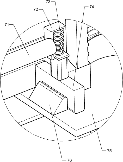
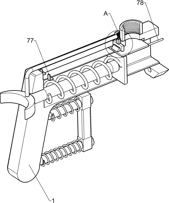
[0028] see image 3 and Figure 4 Compared with Embodiment 1, the main difference of this embodiment is that in this embodiment, a blanking device 7 is also included, and the blanking device 7 includes an L-shaped rod 71, a guide sleeve 72, a third spring 73, a telescopic block 74, Baffle plate 75, first wedge-shaped block 76, second wedge-shaped block 77 and elastic rope 78, and a baffle plate 75 is provided slidingly between the front and rear sides of the housing 1, and the baffle plate 75 is located below the threaded opening of the housing 1 In cooperation with it, a first wedge-shaped block 76 is affixed in the middle of the left side of the top of the baffle plate 75, an L-shaped bar 71 is affixed in the middle of the top of the push handle 51, and a guide sleeve 72 is affixed to the right end of the L-shaped bar 71, and the guide sleeve 72 is of sliding type. The telescopic block 74 is provided, the bottom of the telescopic block 74 is in contact with the first wedge-...


PUM


Abstract

The invention relates to a medicine spraying device, in particular to a medicine spraying device for the respiratory medicine department. The technical problem to be solved is how to design the medicine spraying device for the respiratory medicine department which can comprehensively and uniformly spray medicine to an affected part in a mouth and can emit light to irradiate the mouth, so that medical staff can find the affected part more accurately. The medicine spraying device for the respiratory medicine department comprises a shell, wherein one end of the shell is rotationally connected with a rotary connector; the rotary connector communicates with the interior of the shell; and a threaded opening is formed in one side of the shell. A medicine bottle is screwed on the threaded openingof the shell, medicine liquid flows into the shell, then a push handle is pulled to enable a push plate to move leftwards, the push plate is loosened to move rightwards, the push plate pushes the medicine liquid into the rotary connector, the medicine liquid is sprayed out through a medicine spraying head, and the medicine spraying head can comprehensively spray the medicine liquid to an affectedpart through a rotary device. Therefore, the pesticide spraying is more comprehensive and uniform.

Description


Claims


Application Information

Patent Timeline
Owner 许云霞
Why Eureka
Try Eureka