Ball valve pressing type assembling equipment

An assembly equipment and push-type technology, which is applied in metal processing equipment, metal processing, manufacturing tools, etc., can solve the problems of manually moving the ball and knocking the ball into the valve body, etc., and achieve the effect of reducing the workload

Pending Publication Date: 2020-10-16
刘军强
View PDF6 Cites 23 Cited by
  • Summary
  • Abstract
  • Description
  • Claims
  • Application Information

AI Technical Summary

Problems solved by technology

[0005] In order to overcome the shortcomings of the existing ball valve assembly method that people need to manually move the ball and the valve body, manually knock the ball into the valve body and manually take out the ball valve, the purpose of the present invention is to provide a method that can automatically put the valve body into the valve body. Ball valve press-type assembly equipment that presses the ball into the valve body and automatically extrudes the ball valve

Method used


Image

  • Ball valve pressing type assembling equipment
  • Ball valve pressing type assembling equipment
  • Ball valve pressing type assembling equipment

Examples


Embodiment 1

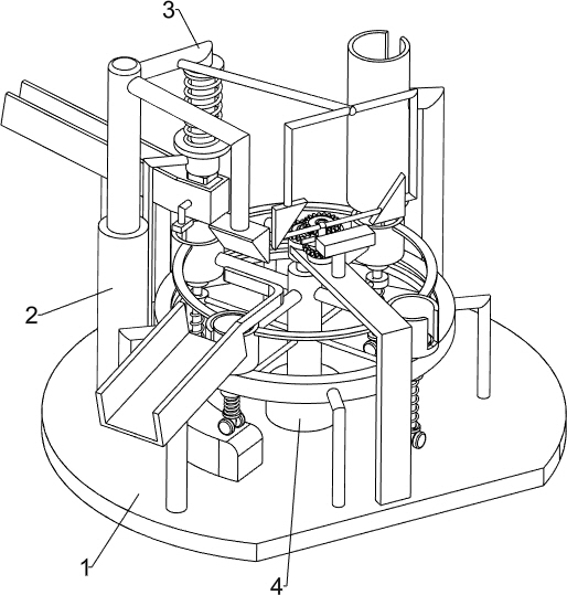
[0027] A ball valve pressing type assembly equipment, such as figure 1 As shown, it includes a base 1, an electric push rod 2, a pressing mechanism 3 and a rotating mechanism 4. An electric push rod 2 is provided on the rear side of the top of the base 1, and a pressing mechanism 3 is connected to the rear side of the top of the base 1. The pressing mechanism 3 is located on the electric push rod. On the right side of the rod 2, the pressing mechanism 3 is connected with the telescopic rod of the electric push rod 2, and a rotating mechanism 4 is installed in the middle of the top of the base 1, and the rotating mechanism 4 is connected with the pressing mechanism 3.

[0028] When people need to assemble the ball valve, people first put the valve body into the parts of the rotating mechanism 4, put the ball into the parts of the pressing mechanism 3, and then start the electric push rod 2, and the telescopic rod of the electric push rod 2 moves downward to drive The parts of t...

Embodiment 2

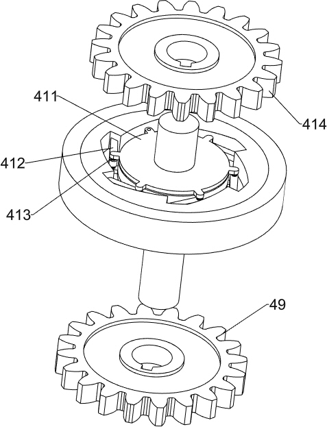
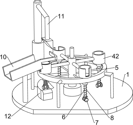
[0030] On the basis of Example 1, such as Figure 2-9 As shown, the pressing mechanism 3 includes a discharge frame 30, a first sliding sleeve 31, a slider 32, a second sliding sleeve 33, a first sliding rod 34, a first spring 35, a connecting rod 36 and a second spring 37, and the base 1. There is a discharge frame 30 on the rear side of the top. The discharge frame 30 is located on the right side of the electric push rod 2. The left and right ends of the front side of the discharge frame 30 are symmetrically connected with the first sliding sleeve 31. The inside of the first sliding sleeve 31 is sliding. A slider 32 is connected, a second spring 37 is connected between the slider 32 and the inner wall of the first sliding sleeve 31, a second sliding sleeve 33 is provided on the rear side of the top of the base 1, and the second sliding sleeve 33 is located between the electric push rod 2 and the Between the discharge frame 30, a first slide bar 34 is slidably connected in th...


PUM


Abstract

The invention relates to assembling equipment, in particular to ball valve pressing type assembling equipment. The aim is to provide ball valve pressing type assembling equipment capable of automatically placing a valve body inside, pressing a ball into the valve body and automatically extruding a ball valve. The ball valve pressing type assembling equipment comprises a base, an electric push rod,a pressing mechanism and a rotating mechanism. The electric push rod is arranged at the top of the base. The side, close to the electric push rod, of the top of the base is connected with the pressing mechanism, and the pressing mechanism is connected with the electric push rod. The rotating mechanism is mounted in the middle of the top of the base and is connected with the pressing mechanism. Bymeans of the ball valve pressing type assembling equipment, the valve body can be automatically placed into a containing frame, the ball can be automatically pressed into the valve body, the assembled ball valve can be automatically extruded out of the containing frame, and therefore the workloads of people can be relieved, and the ball valve assembling efficiency can be improved.

Description

technical field [0001] The invention relates to an assembly device, in particular to a ball valve pressing type assembly device. Background technique [0002] The ball valve is a valve in which the ball is driven by the valve stem and rotates around the axis of the ball valve. The ball valve is mainly used to cut off, distribute and change the flow direction of the medium in the pipeline. It only needs to rotate 90 degrees and a small Turning torque can close tightly, usually used for fluid regulation and control, in the process of making ball valves, it is usually necessary to press the ball into the valve body. [0003] The existing ball valve assembly method is that people manually put the ball on the top of the valve body, and then hold the tool to knock the ball into the bearing valve body. The operation steps are cumbersome, the workload is heavy, and this process is repeated for a long time. During the process of the valve body, it is easy to hit the human hand, and ...

Claims


Application Information

Patent Timeline
Patent Type & Authority Applications(China)
IPC IPC(8): B23P19/02
CPCB23P19/001B23P19/02
Inventor 刘军强
Owner 刘军强
Why Eureka
Try Eureka