
Damping type angle ring pressing machine

A pressing machine and damping technology, applied in the field of transformer production, can solve problems such as tearing of corner rings and progressive forming of difficult corner rings

Active Publication Date: 2020-10-16
江西普雷伊顿电气有限公司
View PDF6 Cites 0 Cited by
  • Summary
  • Abstract
  • Description
  • Claims
  • Application Information

AI Technical Summary

Problems solved by technology

The currently commonly used angle ring forming device is the mold pressing method, but the current mold is usually simple in design, especially the punch, it is difficult to realize the progressive forming of the angle ring, and, in the pressing process, the die is usually relatively static, and the angle The ring wool is also relatively static, and the conditioned wool may stick to the downward moving punch, causing the corner ring to be torn

Method used


Image

  • Damping type angle ring pressing machine
  • Damping type angle ring pressing machine
  • Damping type angle ring pressing machine

Examples


Embodiment Construction

[0019] In order to facilitate the understanding of the present invention, the present invention will be described more fully below with reference to the associated drawings. A preferred embodiment of the invention is shown in the drawings. However, the present invention can be embodied in many different forms and is not limited to the embodiments described herein. Rather, these embodiments are provided so that the disclosure of the present invention will be thorough and complete.

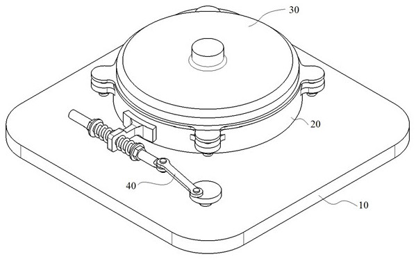
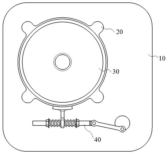
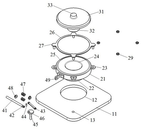
[0020] see Figure 1-Figure 3 The damping type angle ring pressing machine shown includes a base 10, a die assembly 20, a punch assembly 30 and a drive assembly 40, the die assembly 20 is installed on the base 10, and the punch assembly 30 is located on the Above the die assembly 30 , the drive assembly 40 is installed on the base 10 and connected to the die assembly 20 to drive the die assembly 20 to reciprocate.

[0021] The base 10 includes a table top 11, a circular hole 12 and a through hole...


PUM


Abstract

The invention discloses a damping type angle ring pressing machine and belongs to the field of transformer production. The damping type angle ring pressing machine comprises a base, a female mold assembly, a male mold assembly and a driving assembly. The female mold assembly is mounted on the base. The male mold assembly is located above the female mold assembly. The driving assembly is mounted onthe base. The base comprises a table board, a round hole and a through hole. The table board is provided with the round hole. The side portion of the round hole is provided with the through hole. Thefemale mold assembly comprises a female mold, a female mold seat, a molding hole, a gradually-advancing groove and a side portion ring. The bottom of the female mold is provided with the female moldseat. The center of the female mold is provided with the molding hole penetrating the female mold and the female mold seat. The outer edge of the top face of the female mold is provided with the gradually-advancing groove. The side portion ring is mounted on the gradually-advancing groove. The male mold assembly comprises a male mold, a male mold profile and a main joint. The bottom of the male mold is provided with the male mold profile. The driving assembly comprises cross bars, a joint, a crank, a rotating disc, a boss, springs, adjustment nuts and a connecting rod. The middles of the crossbars are connected with the connecting rod. The connecting rod is mounted on the female mold and drives the female mold to move. The cross bars at the two sides of the connecting rod are each provided with the corresponding spring. Each adjustment nut is mounted at the outer side of the corresponding spring.

Description

technical field [0001] The invention belongs to the technical field of transformer production, in particular to a damping type corner ring pressing machine. Background technique [0002] A large number of insulating parts are used in the production of transformers. Among them, the more common and important one is the angle ring. The angle ring is divided into two types: positive angle ring and anti-angle ring. outer circle. The currently commonly used angle ring forming device is the mold pressing method, but the current mold is usually simple in design, especially the punch, it is difficult to realize the progressive forming of the angle ring, and, in the pressing process, the die is usually relatively static, and the angle The ring wool is also relatively static, and the conditioned wool may stick to the downward moving punch, causing the corner ring to be torn. Contents of the invention [0003] The present invention provides a damping type corner ring pressing machin...

Claims


Application Information

Patent Timeline
IPC IPC(8): B30B15/02B30B15/28B30B15/00H01F41/00
CPCB30B15/02B30B15/28B30B15/00H01F41/00
Inventor 屠晓余施高阳
Owner 江西普雷伊顿电气有限公司
Learn More