
Displacement sensor steel wire rope vertical wire outlet device

A displacement sensor and wire rope technology, applied in the field of displacement sensor wire rope vertical outlet device, can solve the problems of easy sticking of impurities and wire ropes that cannot be vertically outlet, and achieve the effect of avoiding damage

Active Publication Date: 2020-10-16
GANZHOU DEYE ELECTRONICS TECH
View PDF10 Cites 0 Cited by
  • Summary
  • Abstract
  • Description
  • Claims
  • Application Information

AI Technical Summary

Problems solved by technology

[0004] In order to overcome the shortcoming that the steel wire rope pulled out of the displacement sensor cannot go out vertically, and impurities are easy to stick to the steel wire rope of the displacement sensor, which affects the movement of the steel wire rope of the displacement sensor, the technical problem is to provide a kind of steel wire rope that can make the displacement sensor go out vertically, and can Displacement sensor wire rope vertical outlet device that removes impurities without affecting the movement of the displacement sensor wire rope

Method used


Image

  • Displacement sensor steel wire rope vertical wire outlet device
  • Displacement sensor steel wire rope vertical wire outlet device
  • Displacement sensor steel wire rope vertical wire outlet device

Examples


Embodiment 1

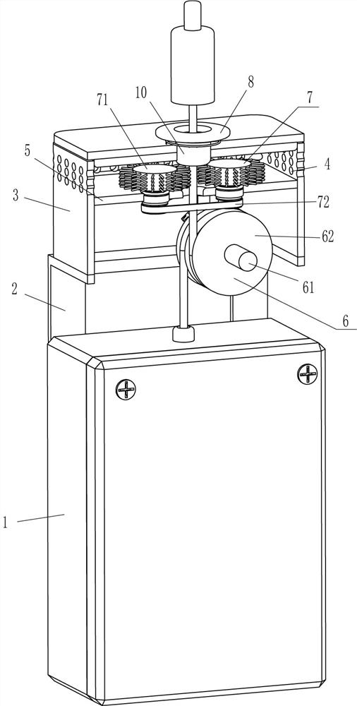
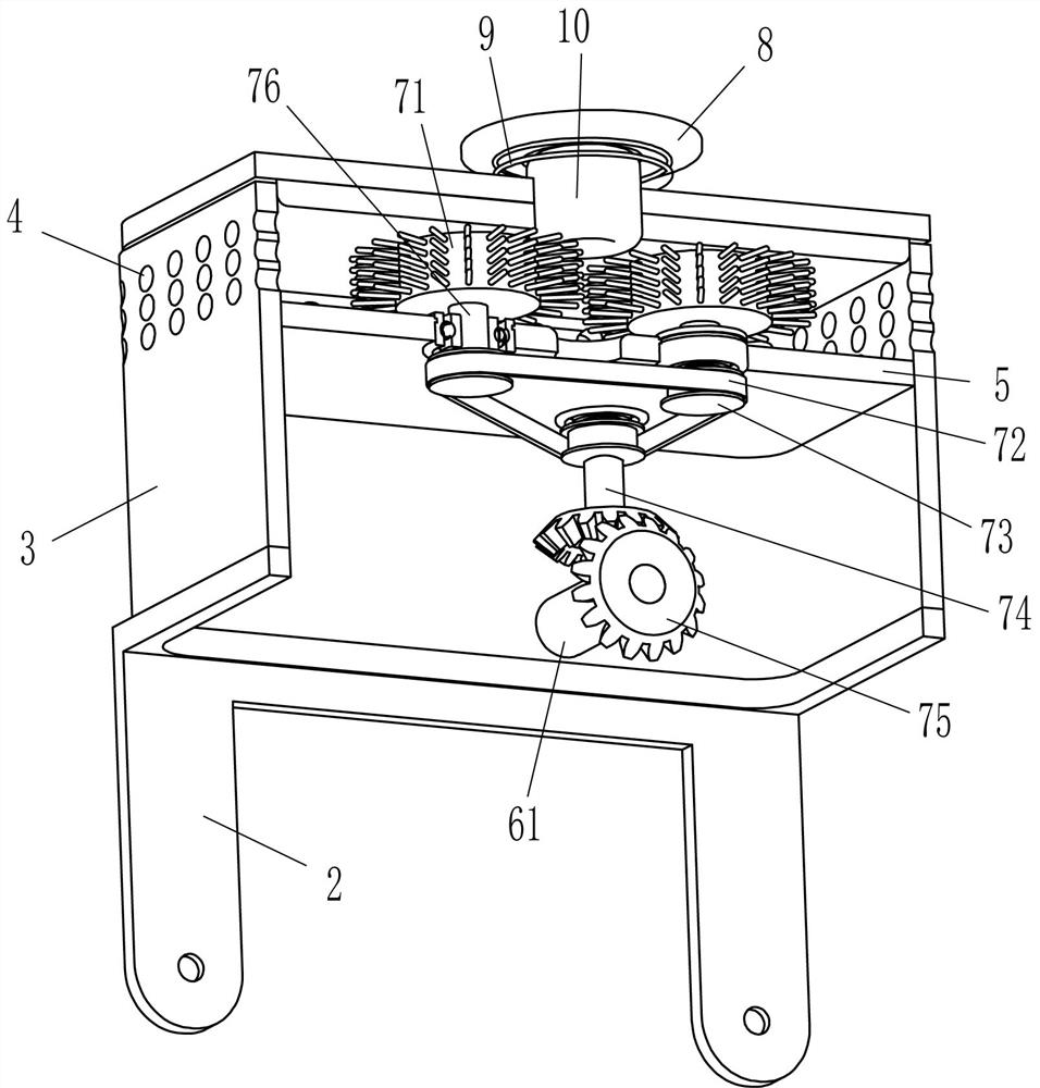
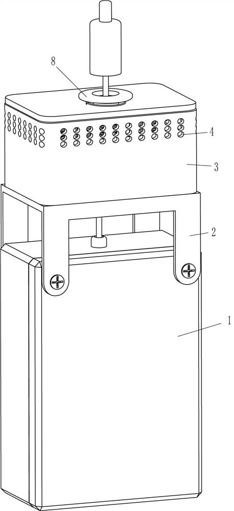
[0020] A vertical outlet device for a displacement sensor wire rope, such as figure 1 and figure 2 As shown, it includes a mounting frame 2, a frame body 3, a fixed plate 5 and a guide mechanism 6. A frame body 3 is installed on the outer top of the mounting frame 2, and through holes 4 are evenly spaced on the upper part of the frame body 3 in the circumferential direction. The frame body 3 A fixed plate 5 is affixed to the top of the inner surface circumferentially, holes are formed on the front side of the top of the frame body 3 and the front side of the fixed plate 5, and a guide mechanism 6 is provided between the lower right side of the front and rear sides of the frame body 3 .

[0021] The guide mechanism 6 includes a first rotating shaft 61 and a winding wheel 62. The first rotating shaft 61 is rotationally connected between the lower right side of the front and rear sides of the frame body 3, and the front portion of the first rotating shaft 61 is fixed with a wind...

Embodiment 2

[0025] On the basis of Example 1, such as figure 2 and image 3 Shown, also comprise clearing mechanism 7, and clearing mechanism 7 comprises hairbrush wheel 71, flat belt 72, belt pulley 73, rotating rod 74, bevel gear 75 and second rotating shaft 76, and fixed plate 5 front sides are left and right symmetrically rotated and worn. A second rotating shaft 76 is connected, and the top of the second rotating shaft 76 is fixedly connected with a brush wheel 71. The right part of the fixed plate 5 rear side is rotatably connected with a rotating rod 74. All are fixedly connected with belt pulley 73, and belt pulley 73 is positioned at fixed plate 5 below, and flat belt 72 is wound around between three belt pulleys 73, and first rotating shaft 61 rear portion circumferential direction and rotating rod 74 bottoms are all fixedly connected with bevel gear 75, up and down The bevel gears 75 on both sides mesh with each other.

[0026] When the wire rope of the displacement sensor 1...

Embodiment 3

[0028] On the basis of embodiment 1 and embodiment 2, such as Figure 1-Figure 3 As shown, a buffer ring 8 and a spring 9 are also included, a spring 9 is affixed to the front middle of the outer top of the frame body 3, and a buffer ring 8 is affixed to the end of the spring 9.

[0029] A ceramic ring 10 is also included, and the ceramic ring 10 is fixedly connected in the hole on the top front side of the frame body 3 , and the ceramic ring 10 is located in the spring 9 .

[0030] When the wire rope of the displacement sensor 1 drives the fixed head to reset, the fixed head is in contact with the buffer ring 8, and due to the effect of the spring 9, the buffer ring 8 buffers the fixed head. In this way, the fixing head can be avoided from being damaged due to violent contact with the frame body 3 .

[0031] When the steel wire rope of the displacement sensor 1 moves, the steel wire rope is in contact with the ceramic ring 10, so that the ceramic ring 10 is more resistant to...


PUM


Abstract

The invention relates to a wire outlet device, in particular to a displacement sensor steel wire rope vertical wire outlet device. Provided is a displacement sensor steel wire rope vertical wire outlet device which enables the steel wire rope of the displacement sensor to be vertically led out and can remove impurities without affecting movement of the steel wire rope of the displacement sensor. the displacement sensor steel wire rope vertical wire outlet device comprises an installation frame, a frame body is installed on one side outside the installation frame, and through holes are formed in the side, away from the installation frame, of the frame body in the circumferential direction at intervals. Through installing the device on a displacement sensor, the steel wire rope of the displacement sensor bypasses the reel and penetrates through the fixing plate and the upper hole of the frame body, so that when people pull the fixing head to drive the steel wire rope of the displacementsensor to move outwards, the reel can enable the steel wire rope to vertically go out, and therefore, the steel wire rope of the displacement sensor can be prevented from deviating to influence measurement.

Description

technical field [0001] The invention relates to an outlet device, in particular to a vertical outlet device for a steel wire rope of a displacement sensor. Background technique [0002] Displacement sensor, also known as linear sensor, is a linear device that belongs to metal induction. The function of the sensor is to convert various measured physical quantities into electricity. In the production process, the measurement of displacement is generally divided into two types: measuring physical size and mechanical displacement. According to the different forms of the measured variable transformation, the displacement sensor can be divided into two types: analog type and digital type. The analog type can be divided into physical property type and structural type. In building construction, in order to measure the data of the building, displacement sensors are used for measurement. [0003] At present, when people use the displacement sensor for measurement, when people pull o...

Claims


Application Information

Patent Timeline
Patent Type & Authority Applications(China)
IPC IPC(8): G01B21/02B65H75/38B65H75/44B08B1/02F16F15/04F16F15/067
CPCG01B21/02B65H75/38B65H75/44F16F15/04F16F15/067B08B1/12B08B1/20B08B1/32
Inventor 李剑徐子超衷梓桑唐宏杨杰
Owner GANZHOU DEYE ELECTRONICS TECH
Learn More