A vertical outlet device for a displacement sensor wire rope
A displacement sensor and wire rope technology, applied in the field of displacement sensor wire rope vertical outlet device, can solve the problems of easy sticking of impurities and wire ropes that cannot be vertically outlet, and achieve the effect of avoiding damage
- Summary
- Abstract
- Description
- Claims
- Application Information
AI Technical Summary
Problems solved by technology
Method used
Image
Examples
Embodiment 1
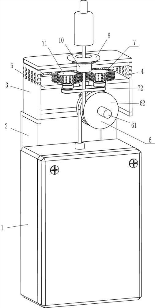
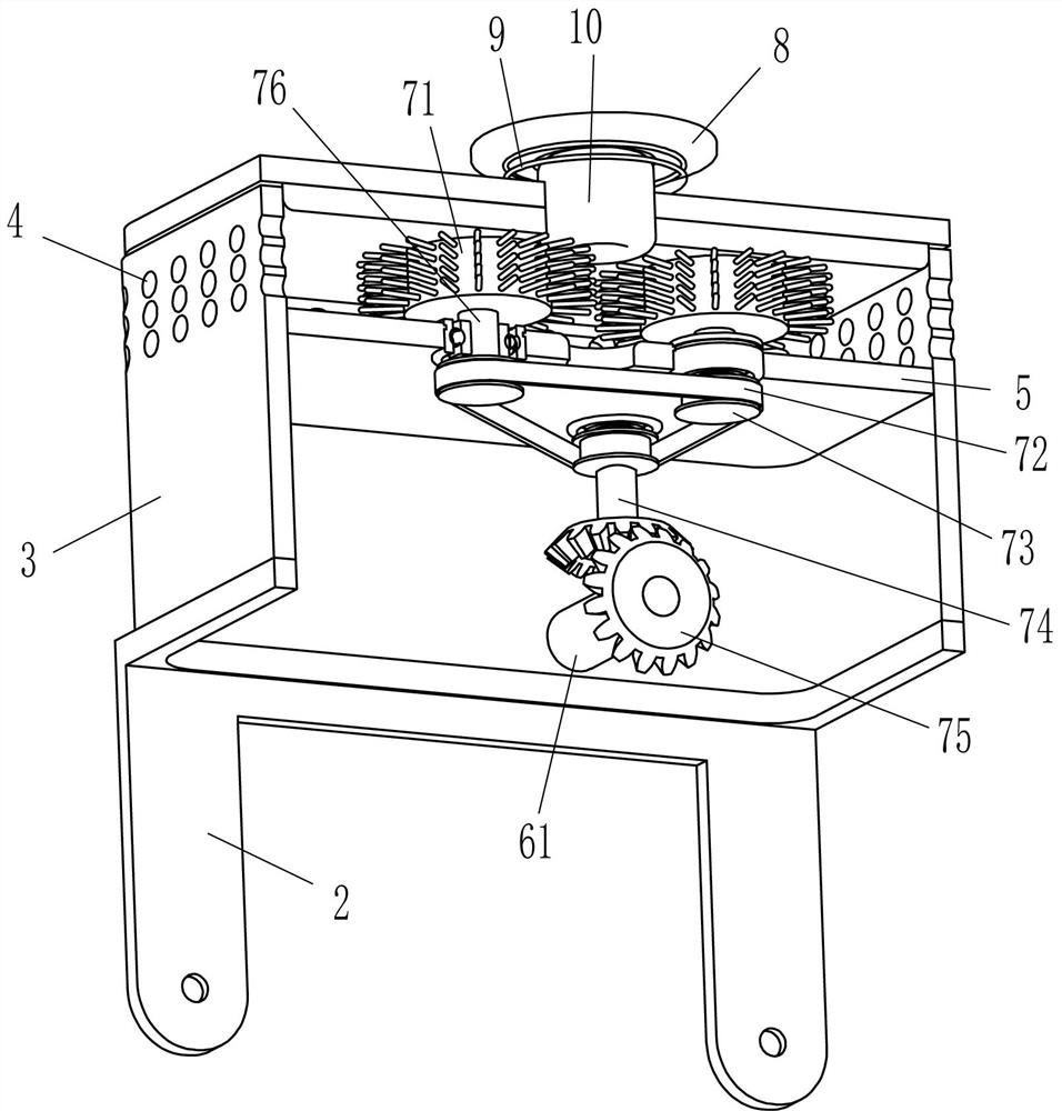
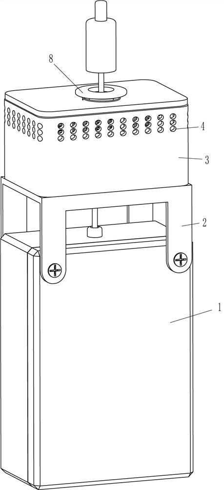
[0020] A vertical outlet device for a displacement sensor wire rope, such as figure 1 and figure 2 As shown, it includes a mounting frame 2, a frame body 3, a fixed plate 5 and a guide mechanism 6. A frame body 3 is installed on the outer top of the mounting frame 2, and through holes 4 are evenly spaced on the upper part of the frame body 3 in the circumferential direction. The frame body 3 A fixed plate 5 is affixed to the top of the inner surface circumferentially, holes are formed on the front side of the top of the frame body 3 and the front side of the fixed plate 5, and a guide mechanism 6 is provided between the lower right side of the front and rear sides of the frame body 3 .
[0021] The guide mechanism 6 includes a first rotating shaft 61 and a winding wheel 62. The first rotating shaft 61 is rotationally connected between the lower right side of the front and rear sides of the frame body 3, and the front portion of the first rotating shaft 61 is fixed with a wind...
Embodiment 2
[0025] On the basis of Example 1, such as figure 2 and image 3 Shown, also comprise clearing mechanism 7, and clearing mechanism 7 comprises hairbrush wheel 71, flat belt 72, belt pulley 73, rotating rod 74, bevel gear 75 and second rotating shaft 76, and fixed plate 5 front sides are left and right symmetrically rotated and worn. A second rotating shaft 76 is connected, and the top of the second rotating shaft 76 is fixedly connected with a brush wheel 71. The right part of the fixed plate 5 rear side is rotatably connected with a rotating rod 74. All are fixedly connected with belt pulley 73, and belt pulley 73 is positioned at fixed plate 5 below, and flat belt 72 is wound around between three belt pulleys 73, and first rotating shaft 61 rear portion circumferential direction and rotating rod 74 bottoms are all fixedly connected with bevel gear 75, up and down The bevel gears 75 on both sides mesh with each other.
[0026] When the wire rope of the displacement sensor 1...
Embodiment 3
[0028] On the basis of embodiment 1 and embodiment 2, such as Figure 1-Figure 3 As shown, a buffer ring 8 and a spring 9 are also included, a spring 9 is affixed to the front middle of the outer top of the frame body 3, and a buffer ring 8 is affixed to the end of the spring 9.
[0029] A ceramic ring 10 is also included, and the ceramic ring 10 is fixedly connected in the hole on the top front side of the frame body 3 , and the ceramic ring 10 is located in the spring 9 .
[0030] When the wire rope of the displacement sensor 1 drives the fixed head to reset, the fixed head is in contact with the buffer ring 8, and due to the effect of the spring 9, the buffer ring 8 buffers the fixed head. In this way, the fixing head can be avoided from being damaged due to violent contact with the frame body 3 .
[0031] When the steel wire rope of the displacement sensor 1 moves, the steel wire rope is in contact with the ceramic ring 10, so that the ceramic ring 10 is more resistant to...
PUM
 Abstract
Description
Claims
Application Information
 - R&D
- Intellectual Property
- Life Sciences
- Materials
- Tech Scout
- Unparalleled Data Quality
- Higher Quality Content
- 60% Fewer Hallucinations
Browse by: Latest US Patents, China's latest patents, Technical Efficacy Thesaurus, Application Domain, Technology Topic, Popular Technical Reports.
© 2025 PatSnap. All rights reserved.Legal|Privacy policy|Modern Slavery Act Transparency Statement|Sitemap|About US| Contact US: help@patsnap.com


