Spiral bevel-gear seed-metering device

A technology of spiral cone and seed metering device, which is applied to the parts of the seeder, etc., can solve the problems of uneven landing, pulsating seed flow, and affecting the uniformity of seeding.

Inactive Publication Date: 2020-10-20
YANGZHOU UNIV
View PDF8 Cites 0 Cited by
  • Summary
  • Abstract
  • Description
  • Claims
  • Application Information

AI Technical Summary

Problems solved by technology

The outer groove wheel type seed meter is the most commonly used seed meter on the seeder at present. It has the advantages of simple structure, good versatility, and stable seeding rate. The seeds are forced to be discharged by moving the seeds, and the grooved wheel rotates to the groove to discharge more seeds, and the tooth ridges are less, so the seed flow is pulsating, which affects the uniformity of the seeds.
[0003] In addition, after the seeds leave the metering device, they fall freely in the seed guide tube under the action of gravity. In the process, the seeds are inevitably disturbed by the air flow, and phenomena such as collision, bounce and friction occur at the same time. The above factors are all Change the uniformity of the initial throwing of the seeds from the seed meter, resulting in uneven landing points and uneven plant spacing after the seeds leave the seed tube, which affects the growth of the crops to a certain extent

Method used


Image

  • Spiral bevel-gear seed-metering device
  • Spiral bevel-gear seed-metering device

Examples


Embodiment Construction

[0014] The present invention will be further described below in conjunction with accompanying drawing:

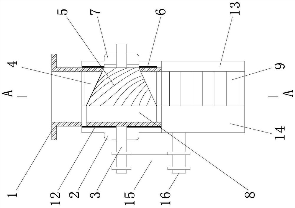
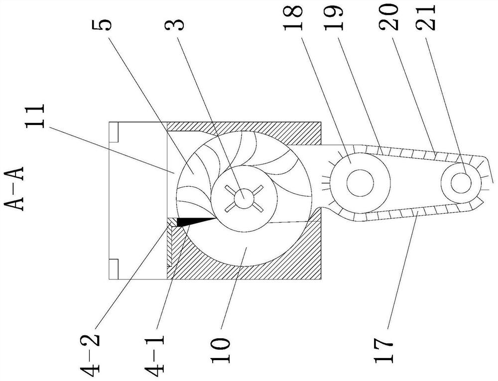
[0015] Such as Figure 1-2 As shown, a spiral bevel tooth metering device, the seed metering device consists of a housing 1, a blocking wheel end cover 2, a seeding shaft 3, a seed cleaning device 4, a seeding wheel 5, a first retaining ring 6, a seeding wheel End cover 7, blocking wheel 8, seed guiding device 9, seed protection plate 10, second retaining ring 12 and transmission belt 15 are connected to form; There is a seed opening 11, the seed shaft 3 is arranged in the shaft hole of the seed wheel 5, one end of the seed shaft 3 is connected to the external motor transmission, and the seed cleaning device 4 is composed of a seed cleaning brush 4-1 and a connecting plate 4- 2, the seed cleaning brush 4-1 is fixedly connected to the housing 1 through the connecting plate 4-2, the seed guide device 9 is arranged below the seed wheel 5, and the seed guide device 9 consists ...


PUM


Abstract

The invention provides a spiral bevel-gear seed-metering device, belonging to the technical field of agricultural machinery seeding machinery. The spiral bevel-gear seed-metering device structurally comprises a shell, a blocking wheel end cover, a seed-metering shaft, a seed cleaning device, a seed-metering wheel, a first retainer ring, a seed-metering wheel end cover, a blocking wheel, a seed guiding unit, a seed protecting plate, a second retainer ring and a belt which are in connection. The spiral bevel-gear seed-metering device is simple in structure and clear in operating principle. Seedsfall into a seed filling area from a seed-metering opening; the seed-metering shaft drives a spiral bevel-gear seed-metering wheel to rotate; the seed protecting plate is tightly attached to the outer contour surface of the spiral bevel-gear seed-metering wheel; the seed-metering wheel rotates to a seed falling area; the seeds enter the seed guiding unit and fall into a seed guiding groove; a seed guiding driving wheel drives a seed guiding driving wheel belt through the seed-metering shaft to move; the seeds in the seed guiding groove are driven by a seed guiding conveying belt to reach a seed feeding position; and the seeds fall into a seed ditch under the action of gravity. The spiral bevel-gear seed-metering device provided by the invention has the following advantages: seed filling is facilitated; meanwhile, the uniformity of seed metering is improved; the problem of pulsation is effectively solved; and through arrangement of a belt type conveying seed guiding unit, the plant spacing after seed feeding can be guaranteed to be uniform and accurate, and the plant spacing qualified rate of the seeds is greatly improved.

Description

technical field [0001] The invention belongs to the technical field of agricultural machinery sowing machinery, and relates to a seed metering device, in particular to a spiral bevel tooth seed metering device. Background technique [0002] The seed meter is the core component of the seeder and the main factor that determines the characteristics of the seeder and the quality of sowing. The working performance of the seed meter will directly affect the working efficiency of the seeder and the quality of crop emergence. The outer groove wheel type seed meter is the most commonly used seed meter on the seeder at present. It has the advantages of simple structure, good versatility, and stable seeding rate. The seeds are forced to be sorted by moving the seeds, and the grooved wheel rotates to the groove to discharge more seeds, and the tooth ridges are less, so the seed flow is pulsating, which affects the uniformity of seeding. [0003] In addition, after the seeds leave the ...

Claims


Application Information

Patent Timeline
Patent Type & Authority Applications(China)
IPC IPC(8): A01C7/20
CPCA01C7/20
Inventor 缪宏韩非袁锐张燕军张善文苏伟戈林泉童俊华齐江涛刘思幸
Owner YANGZHOU UNIV
Why Eureka
Try Eureka