Control box quick assembly structure of lifting table and lifting table frame

A technology for assembling a structure and a control box, applied in the field of lifting table accessories, can solve the problems of large changes in the structure of the control box, troublesome and laborious replacement of the position of the control box, etc.

Pending Publication Date: 2020-10-20
ZHEJIANG JIECHANG LINEAR MOTION TECH
View PDF1 Cites 2 Cited by
  • Summary
  • Abstract
  • Description
  • Claims
  • Application Information

AI Technical Summary

Problems solved by technology

[0004] The current installation structure of the control box, if it is the way of screw fasteners, is more troublesome to assemble, and it needs to be realized by tools, and it is also laborious. The structure of the box itself changes greatly, and the cost of input is relatively high
At the same time, there is still a problem in these two methods, that is, the installation position of the control box itself is relatively fixed, and it is troublesome if the position of the control box needs to be replaced.

Method used


Image

  • Control box quick assembly structure of lifting table and lifting table frame
  • Control box quick assembly structure of lifting table and lifting table frame
  • Control box quick assembly structure of lifting table and lifting table frame

Examples


Embodiment 1

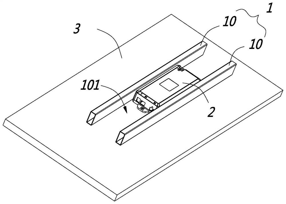
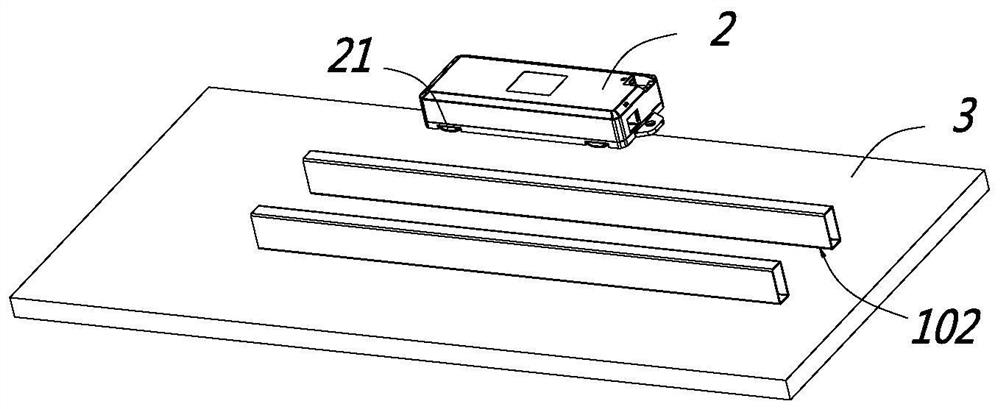
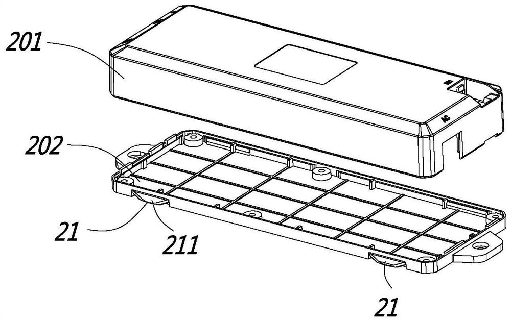
[0033] Such as Figure 1 to Figure 6 As shown, this embodiment shows a quick assembly structure of the lift table control box 2, including a beam 1 and a control box 2, the beam 1 is used to be installed under the table 3, and the beam 1 is provided with a container The accommodating groove 101 of the control box 2, on the inner side wall of the accommodating groove 101 and the corresponding outer side wall of the control box 2, one of them is provided with a slide rail groove 102, and the other is provided with a positioning protrusion 21. In an assembled state, the positioning protrusion 21 is clamped into the slide rail groove 102, and the slide rail groove 102 allows the positioning protrusion 21 to slide laterally therein.

[0034] In this embodiment, on the inner wall of the accommodating groove 101 and the outer wall of the control box 2, one of them is provided with a positioning protrusion 21, and the other is provided with a slide rail groove 102. When assembling, th...

Embodiment 2

[0048] Such as Figure 7 As shown, the difference between the present embodiment and the first embodiment mainly lies in the design of the slide rail groove 102. The first embodiment is a more preferred solution, which can keep the cost very low, while the slide rail in this embodiment The groove 102 is an independently designed bar-shaped groove. The main purpose of this design is that the stability of the slide rail groove 102 is better, because similar to the arc chamfer 103 in the first embodiment, its size is relatively limited. If the arc chamfer 103 is small, the depth of the slide rail groove 102 is relatively small, so the slide rail groove 102 in the first embodiment is relatively limited by the size of the arc chamfer 103 itself.

[0049] In this embodiment, the slide rail groove 102 is an independent bar-shaped groove, and its size is not limited to the arc chamfer 103. The cost is higher than that of Embodiment 1, but the stability is better, and at the same time ...

Embodiment 3

[0051] This embodiment is a table frame for a lift table, which includes a beam, lifting columns installed on both sides of the beam, and a control box installed in the beam, the control box controls the lifting column to go up and down, and the control box is used between the beam and the beam. Embodiment 1 or Embodiment 2 or a rapid assembly structure equivalent thereto.


PUM


Abstract

The invention discloses a control box quick assembly structure of a lifting table. The invention belongs to the field of electric lifting table accessories. The structure comprises a cross beam and acontrol box, and the cross beam is used for being installed below a table board. A containing groove for containing the control box is formed in the cross beam, a sliding rail groove is formed in oneof the inner wall of the containing groove and the outer side wall of the control box, a positioning protrusion is arranged on the other one of the inner wall of the containing groove and the outer side wall of the control box, the positioning protrusion is clamped in the sliding rail groove in an assembled state, and the positioning protrusion can transversely slide in the sliding rail groove. The invention further discloses a lifting table frame adopting the control box quick assembly structure, and the control box quick assembly structure and the lifting table frame have the advantages thatthe control box is more convenient to assemble, and meanwhile the cost is lower.

Description

【Technical field】 [0001] The invention relates to a quick assembly structure of a lift table control box and a lift table frame, belonging to the field of lift table accessories. 【Background technique】 [0002] Desks are daily furniture widely used by people in work, study and life. There are many types of desks, such as computer desks, study desks, office desks and the like. With the improvement of people's quality of life, the requirements for the comfort and convenience of the table are getting higher and higher. Therefore, in order to meet the requirements of users of different heights, a height-adjustable lifting table has appeared on the market at present, and in order to facilitate people's operation, the function of electric lifting has been added to the lifting table in the prior art, that is, the electric lifting table. Lift table. [0003] The basic structure of the current electric lifting table is to include a table board, a beam is arranged under the table bo...

Claims


Application Information

Patent Timeline
Patent Type & Authority Applications(China)
IPC IPC(8): A47B13/00A47B9/00
CPCA47B13/00A47B9/00
Inventor 许欣章浙康
Owner ZHEJIANG JIECHANG LINEAR MOTION TECH
Why Eureka
Try Eureka