Test tube placement cabinet for experimental instruments
A technology of experimental instruments and test tubes, which is applied in the field of storage cabinets, can solve the problems of inconvenient removal and easy movement of test tubes, and achieve the effect of convenient removal and avoiding damage
- Summary
- Abstract
- Description
- Claims
- Application Information
AI Technical Summary
Problems solved by technology
Method used
Image

Examples
Embodiment 1
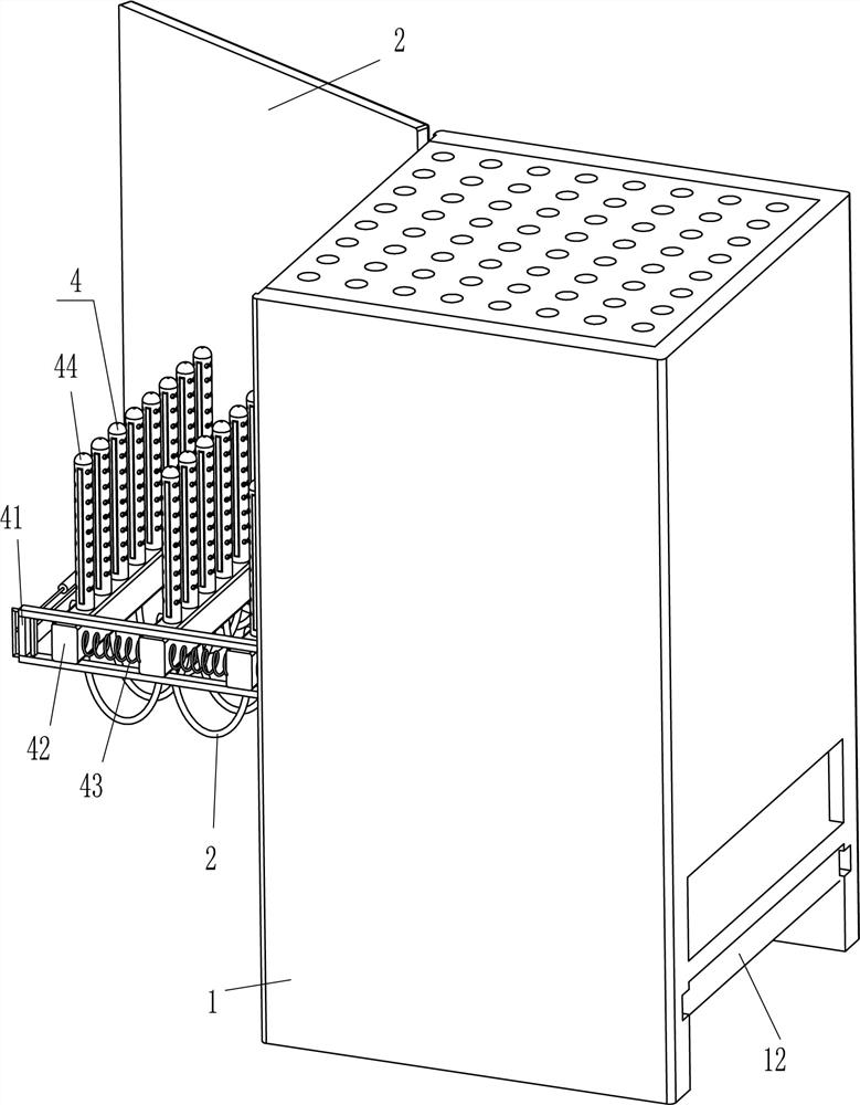
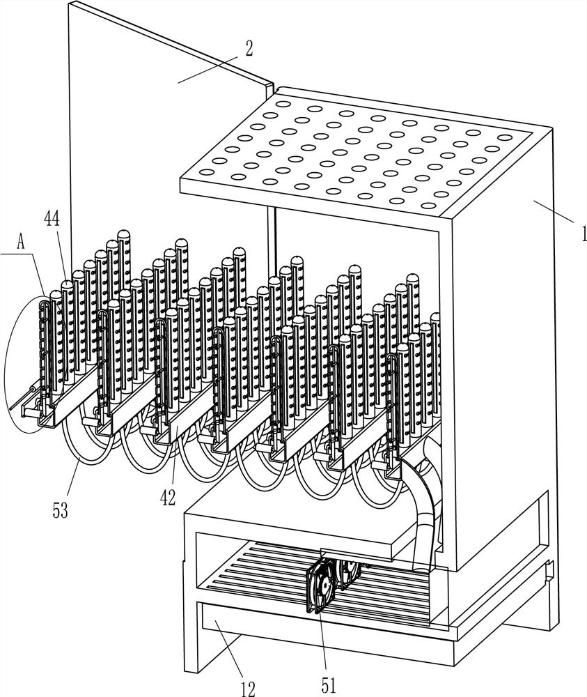
[0024] refer to Figure 1-Figure 4 , a test tube placement cabinet for experimental instruments, including a cabinet body 1, a cabinet door 2, a guide rail 3, a placement mechanism 4 and a drying mechanism 5, the cabinet door 2 is hinged on the upper rear side of the left side of the cabinet body 1, and the cabinet door 2 In cooperation with the cabinet body 1, guide rails 3 are fixedly connected to the lower parts of the front and rear sides of the cabinet body 1, a placement mechanism 4 is provided between the front and rear side guide rails 3, and a drying mechanism 5 is provided at the lower part of the cabinet body 1. The drying mechanism 5 is connected with placement mechanism 4.
[0025] Placement mechanism 4 includes u-shaped frame 41, movable hollow block 42, first spring 43 and porous pipe 44, and the sliding type is provided with u-shaped frame 41 between the front and rear sides guide rails 3, between the front and rear sides guide rails 3 There are seven movable ...
Embodiment 2
[0031] refer to Figure 3-Figure 7 Compared with Embodiment 1, the main difference of this embodiment is that in this embodiment, a clamping mechanism 6 is also included, and the clamping mechanism 6 includes an L-shaped contact rod 61, an arc-shaped block 62, a fixed rod 63, and a two-way hollow sleeve. 64, movable rod 65, wedge-shaped block 66, sponge clip 67 and second spring 68, fixed rod 63 is fixedly connected in the middle of the inner top of porous pipe 44, and the even space embedded on the fixed rod 63 is provided with two-way hollow sleeve 64, two-way The sliding type in the hollow sleeve 64 is provided with a movable rod 65, a second spring 68 is connected between the inner end of the movable rod 65 and the inner side of the two-way hollow sleeve 64, and a sponge clip 67 is fixedly connected between the outer ends of all the front side movable rods 65 , between the outer ends of the rear side movable rods 65, there is also a fixed connection of a sponge clip 67, th...
Embodiment 3
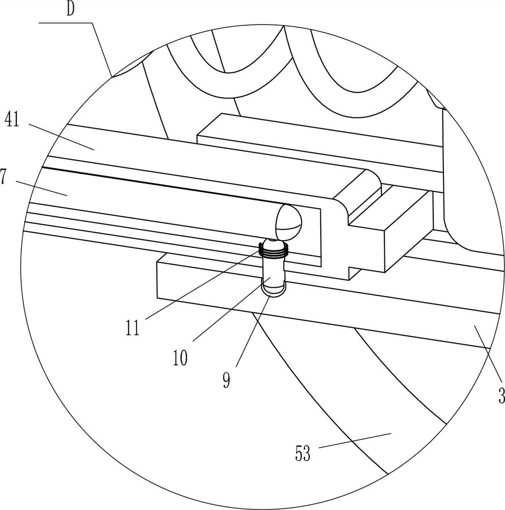
[0034] refer to figure 2 , image 3 with Figure 8 , compared with embodiment 1 and embodiment 2, the main difference of this embodiment is that in this embodiment, a u-shaped bar 7, a pull bar 8, a clamping bar 10 and a third spring 11 are also included, and the front and rear parts of the u-shaped frame 41 are both The sliding type is provided with a u-shaped bar 7, and a pull bar 8 is fixedly connected between the left parts of the u-shaped bar 7 on the front and rear sides. The end is in contact with the u-shaped bar 7, and the third spring 11 is wound between the inside of the bar 10 and the inside of the u-shaped frame 41, and the left and right sides of the top and bottom of the guide rail 3 are provided with clips that cooperate with the bar 10. Slot 9.
[0035] Also comprise sponge piece 12, cabinet body 1 outer bottom sliding type is provided with sponge piece 12, and sponge piece 12 cooperates with hot air blower 51.
[0036] Initially, the third spring 11 is i...
PUM
 Abstract
Description
Claims
Application Information
 - R&D
- Intellectual Property
- Life Sciences
- Materials
- Tech Scout
- Unparalleled Data Quality
- Higher Quality Content
- 60% Fewer Hallucinations
Browse by: Latest US Patents, China's latest patents, Technical Efficacy Thesaurus, Application Domain, Technology Topic, Popular Technical Reports.
© 2025 PatSnap. All rights reserved.Legal|Privacy policy|Modern Slavery Act Transparency Statement|Sitemap|About US| Contact US: help@patsnap.com