Storage battery pack parameter measurement circuit

A technology for parameter measurement and battery pack, applied in battery circuit devices, measuring electricity, measuring electrical variables, etc., can solve the problems of imperfect detection methods and inability to accurately detect abnormal single batteries.

Pending Publication Date: 2020-10-20
桂林智源电力电子有限公司
View PDF0 Cites 0 Cited by
  • Summary
  • Abstract
  • Description
  • Claims
  • Application Information

AI Technical Summary

Problems solved by technology

Due to the complexity inside the battery, this detection method is a

Method used


Image

  • Storage battery pack parameter measurement circuit

Examples


Example Embodiment

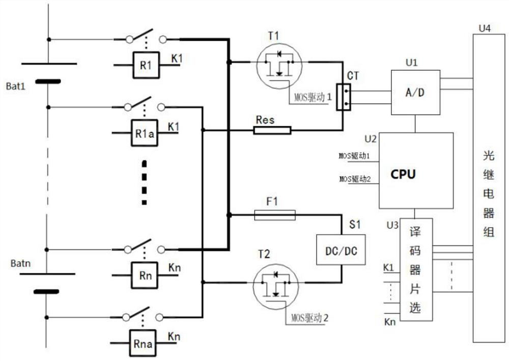
[0015] See figure 1 , Example 1: A battery pack parameter measurement circuit, including power Bat, relay R1-Rn, relay R1a-Rna, MOS tube T1, MOS tube T2, current sensor CT, A / D chip U1, CPU central processing unit U2 , Decoder chip selection chip U3 and photorelay group U4, the power source Bat is composed of battery Bat1-battery Batn in series, the positive electrode of battery Bat1 is connected to the drain of MOS tube T1 and charging fuse F1 through the contact of relay R1, battery The anode of the Batn is connected to the drain of the MOS transistor T1 and the charging fuse F1 through the contact of the relay Rn. The source of the MOS transistor T1 is connected to the current sensor CT. The current sensor CT is also connected to the A / D chip U1, and the A / D chip U1 is also connected. Connect the CPU central processor U2 and the photorelay group U4 respectively. The negative electrode of the battery Bat1 is connected to the discharge resistor Res and the drain of the MOS tub...

Example Embodiment

[0027] Embodiment 2, based on the above embodiment 1, to solve the above third technical problem, the technical solution adopted by the present invention is as follows: the measurement and control instrument of the present invention detects the voltage and ohmic internal resistance of each battery in the battery pack online; the CPU central processing The controller, embedded software and logic, combined with the parameter setting of the system, controls the equalization and activation of the battery to recharge.

[0028] In the equalizing charging scheme, the embedded software reads the cell voltage in the battery pack, and the software logic judges that the unbalanced degree of the battery is greater than the system parameter setting value, and starts the equalizing charge of the battery with the lowest cell voltage with a constant current charging current of 2A.

[0029] In the activation charging scheme, the embedded software reads the single ohmic internal resistance in the bat...


PUM


Abstract

The invention discloses a storage battery pack parameter measuring circuit. The circuit comprises a power supply Bat, relays R1 to Rn, relays R1a to Rna, an MOS transistor T1, an MOS transistor T2, acurrent sensor CT, an A/D chip U1, a CPU central processor U2, a decoder chip selection chip U3 and an optical relay group U4. The power supply Bat is composed of a storage battery Bat1 to a storage battery Batn which are connected in series. The positive electrode of the storage battery Bat1 is connected with the drain electrode of the MOS transistor T1 and a charging fusible core F1 through thecontact of the relay Rn, and the positive electrode of the storage battery Batn is connected with the drain electrode of the MOS transistor T1 and the charging fusible core F1 through the contact of the relay Rn. The circuit provided by the invention has the beneficial effects that 1 the storage battery parameters acquired by the circuit is more accurate and higher in precision; and 2 the storagebatteries with outdated performances in the storage battery pack can be subjected to balanced charging and activated charging, so that the service lives of the storage batteries can be prolonged;

Description

technical field [0001] The invention relates to the field of storage battery technology, in particular to a battery pack parameter measurement circuit. Background technique [0002] In the 220V / 110V DC power panel, UPS power panel and EPS power panel, the valve-regulated lead-acid battery is used in a large amount. Generally, a dozen or dozens of single batteries are connected in series to form a battery pack. These power screens provide backup energy. When the external AC power is normal, the rectification and charging module of the power panel is connected to both ends of the battery pack to charge the battery pack. When the grid AC power fails, the battery pack provides uninterrupted energy to the power panel. [0003] The rectifying and charging module is connected in parallel to the two ends of the whole group of batteries to charge the battery pack, and the charging current flows through each single battery connected in series in the whole group. When there are smal...

Claims


Application Information

Patent Timeline
IPC IPC(8): G01R31/385G01R31/379G01R31/396H02J7/00
CPCG01R31/379G01R31/385G01R31/396H02J7/0019
Inventor 丁进科彭云华李幼峰
Owner 桂林智源电力电子有限公司
Why Eureka
Try Eureka