
A stably placed identification plate based on transmission adjustment

A signboard and stable technology, applied in the field of signboards that are placed firmly, can solve the problems of being unable to be placed, sucking in, being difficult to pick up, and inconvenient, and achieving the effect of stable placement and convenient picking up.

Active Publication Date: 2022-03-15
HEFEI TIKON SIGNAGE SIGNS CO LTD
View PDF14 Cites 0 Cited by
  • Summary
  • Abstract
  • Description
  • Claims
  • Application Information

AI Technical Summary

Problems solved by technology

However, the signboard is easy to slip off on smooth tiles and floors, or it cannot be placed and falls over, or it is blown down by the outside wind
[0004] Although the suction cup can be directly installed on the signboard, it can be adsorbed on the ground, but it is more laborious and inconvenient to attract and pick up

Method used


Image

  • A stably placed identification plate based on transmission adjustment
  • A stably placed identification plate based on transmission adjustment
  • A stably placed identification plate based on transmission adjustment

Examples


Embodiment 1

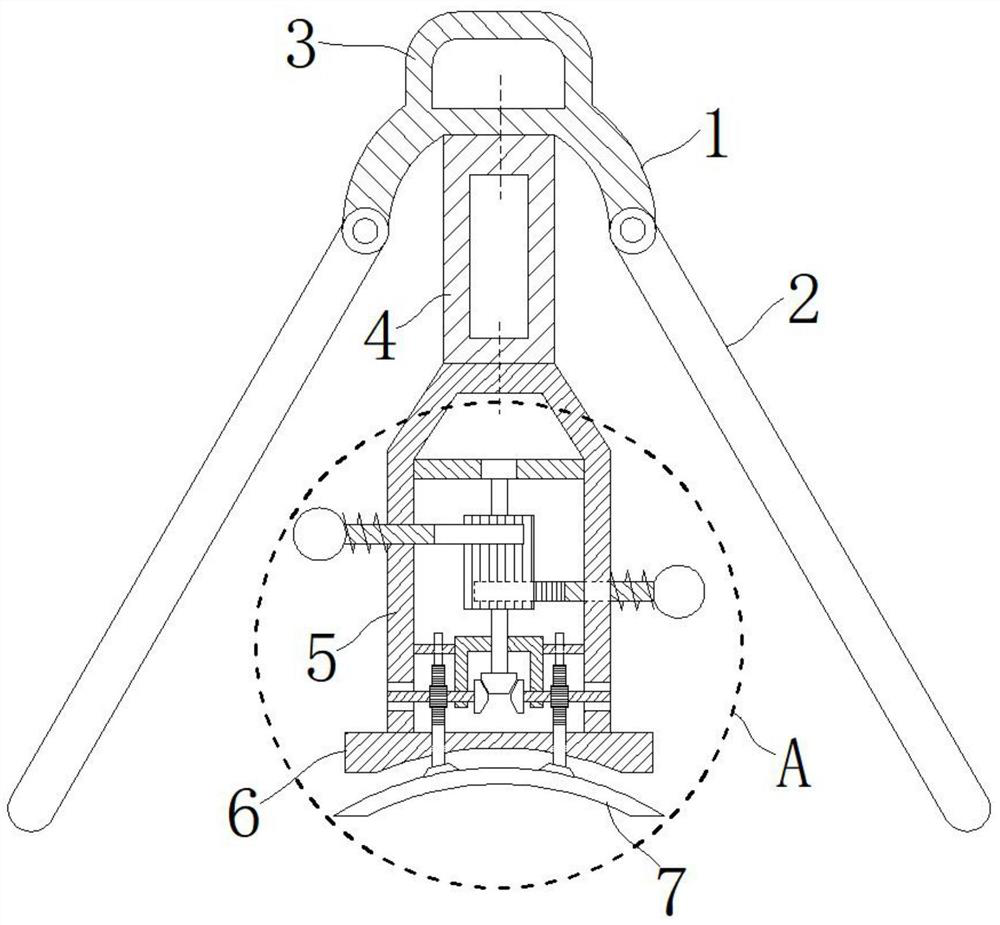
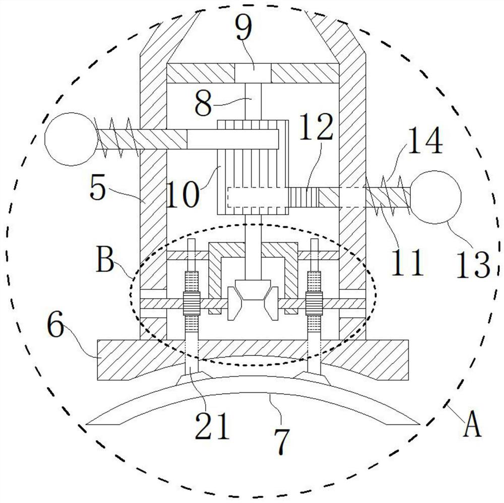
[0026] The present invention is a stably placed identification plate based on transmission adjustment, such as figure 1 , figure 2 , image 3 The upper side of the upper mounting base 1 is provided with an upper handle 3, and the lower ends of both sides of the upper mounting base 1 are movably connected with a movable identification plate 2 through a rotating shaft. It is characterized in that: the lower side of the upper mounting base 1 is fixed with bolts. The middle part connects the frame body 4; the lower side of the middle part connection frame body 4 is fixedly installed with a lower installation base frame body 5 by bolts; the lower end of the lower part installation base frame body 5 is fixedly connected with a bottom installation base plate 6; Bottom rubber suction cup7.

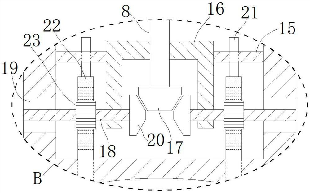
[0027] The inner side of the lower installation base frame body 5 is provided with a main rotating tooth mouth cylinder 10; the two side plates of the lower installation base frame body 5 are m...

Embodiment 2

[0034]In the structure of the present invention, when the signboard is dropped directly and contacts the floor tiles, the outer tension spring 14 pushes the laterally movable drive rod 11 outward, and the laterally inner toothed bar 12 drives the main rotating toothed cylinder 10 to rotate clockwise , driving the bottom rubber suction cup 7 to press down, as if it is automatically sucked in with the floor tiles, without too much intervention from people.

[0035] Upper handle 3 is convenient to mention signboard, and when signboard is mentioned, self gravity of movable signboard 2 causes extruding to cross bar outer limit sphere 13 (if self gravity of movable signboard 2 is not enough, just push forward with pin , press the movable identification plate 2 inwardly), the laterally inner tooth mouth strip plate 12 drives the main rotating tooth mouth cylinder 10 to rotate counterclockwise, passes through, and drives the first end side bevel gear 17, the second end side bevel gear ...


PUM


Abstract

The invention discloses a stably placed identification plate based on transmission adjustment, and relates to the field of identification plate installation mechanisms. In the present invention: the lower ends of both sides of the upper installation base are movably connected with movable identification plates, the lower side of the upper installation base is fixed with a middle connection frame by bolts; A frame body; the lower end of the lower mounting base frame body is fixedly connected with a bottom mounting base plate; a bottom rubber sucker is arranged below the bottom mounting base plate. The present invention drives the third longitudinal toothed plate by driving the second fixed gear to carry out lifting adjustment, and can rely on its own gravity and the elastic force of the outer tension spring to quickly engage with the floor tiles when placing the signboard; when the signboard is picked up, Through lateral pressure, the rubber suction cup at the bottom can be assisted to pull up the signboard, and the signboard can be picked up in the longitudinal direction, making the signboard more stable and easy to pick up in indoor places or some smooth ground scenes.

Description

technical field [0001] The invention belongs to the field of identification plate installation mechanisms, in particular to a stably placed identification plate based on transmission adjustment. Background technique [0002] In many indoor or outdoor scenes, there may be many places that need the attention of pedestrians and vehicles, such as wet floors, steps, glass doors that have just been dragged, or maintenance road conditions ahead, water accumulation, etc. Information from people and vehicles. [0003] Especially on some smooth tiles and floors, signs need to be placed in dangerous areas. However, the signboard is easy to slip away on smooth tiles and floors, or it cannot be placed and toppled over, or it is blown down by the outside wind. [0004] Although the suction cup directly installed on the signboard can be adsorbed on the ground, it is more laborious and inconvenient to attract and pick up. Contents of the invention [0005] The purpose of the present in...

Claims


Application Information

Patent Timeline
Patent Type & Authority Patents(China)
IPC IPC(8): G09F7/12G09F7/18
CPCG09F7/12G09F7/18G09F2007/122
Inventor 付健健胡洪文胡正胜
Owner HEFEI TIKON SIGNAGE SIGNS CO LTD
Learn More