Underground pipe gallery cable and wire laying traction equipment for municipal construction engineering
A technology for construction projects and underground pipe corridors, applied in the direction of cable laying equipment, etc., can solve the problems that cables and wires cannot be reached, and cables and wires are blocked and piled up
- Summary
- Abstract
- Description
- Claims
- Application Information
AI Technical Summary
Problems solved by technology
Method used
Image
Examples
Embodiment 1
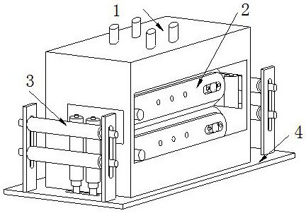
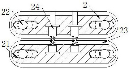
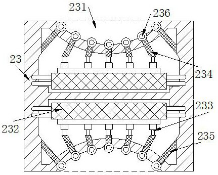
[0029] The present invention provides a traction device for laying cables and wires in an underground pipe gallery of a municipal construction project. The structure includes a traction box 1, a pressure plate 2, a guide roller 3 and a base 4. 2 Cooperate installed inside the traction box 1, the bottom of the guide roller 3 is connected to the top of the base 4 by bolts and located on both sides of the traction box 1, the pressure plate 2 includes a chute 21, a sliding roller 22, a clamping belt 23, and a positioning plate 24, the chute 21 is embedded on the left and right sides of the pressure plate 2, the sliding roller 22 is connected to the inside of the chute 21 through a gap, the inner side of the clamping belt 23 is nested on the outer surface of the sliding roller 22, the positioning The upper and lower ends of the plate 24 are respectively embedded between the upper and lower pressure plates 2. There are two pressure plates 2, and the sliding roller 22 runs through the...
Embodiment 2
[0035]In the figure, its structure includes a traction box 1, a pressure plate 2, a guide roller 3, and a base 4, the bottom of the traction box 1 is welded above the base 4, the pressure plate 2 is fitted inside the traction box 1, and the bottom of the guide roller 3 Connected to the top of the base 4 by bolts and located on both sides of the traction box 1, the pressure plate 2 includes a chute 21, a sliding roller 22, a clamping belt 23, and a positioning plate 24, and the chute 21 is embedded in the left and right sides of the pressure plate 2 On the surface, the sliding roller 22 is connected to the inside of the chute 21 through a gap, the inner side of the clamping belt 23 is nested on the outer surface of the sliding roller 22, and the upper and lower ends of the positioning plate 24 are respectively embedded and fixed between the upper and lower pressure plates 2. Between, there are two pressing plates 2, and the sliding roller 22 runs through the inside of the pressi...
PUM
 Abstract
Description
Claims
Application Information
 - R&D
- Intellectual Property
- Life Sciences
- Materials
- Tech Scout
- Unparalleled Data Quality
- Higher Quality Content
- 60% Fewer Hallucinations
Browse by: Latest US Patents, China's latest patents, Technical Efficacy Thesaurus, Application Domain, Technology Topic, Popular Technical Reports.
© 2025 PatSnap. All rights reserved.Legal|Privacy policy|Modern Slavery Act Transparency Statement|Sitemap|About US| Contact US: help@patsnap.com


