
Cold-rolling pipe mill transmission device with mass balance mechanism

A cold-rolled pipe mill, mass balance technology, applied in the driving device for metal rolling mill, metal rolling, metal rolling, etc., can solve the problem of large crankshaft forging difficult torsion joint effect, high manufacturing cost of rolling mill, manufacturing Require high-level problems to avoid bending force and twisting force, improve service life, and eliminate inertial force

Active Publication Date: 2017-11-24
广东科莱博科技有限公司
View PDF5 Cites 2 Cited by
  • Summary
  • Abstract
  • Description
  • Claims
  • Application Information

AI Technical Summary

Problems solved by technology

[0008] The transmission device of the KPW series cold rolling mill adopts a horizontal mass balance mechanism, although the inertial force generated by the reciprocating motion of the frame can be effectively balanced, but the large crankshaft is difficult to forge, and it is subjected to combined bending and torsion during work. high manufacturing requirements
Due to the use of the crankshaft, which is difficult to process and requires high precision, not only the manufacturing cost of the rolling mill remains high, but the manufacturing cycle is also very long

Method used


Image

  • Cold-rolling pipe mill transmission device with mass balance mechanism
  • Cold-rolling pipe mill transmission device with mass balance mechanism
  • Cold-rolling pipe mill transmission device with mass balance mechanism

Examples


Embodiment Construction

[0022] The present invention will be further described in detail below through specific embodiments in conjunction with the accompanying drawings.

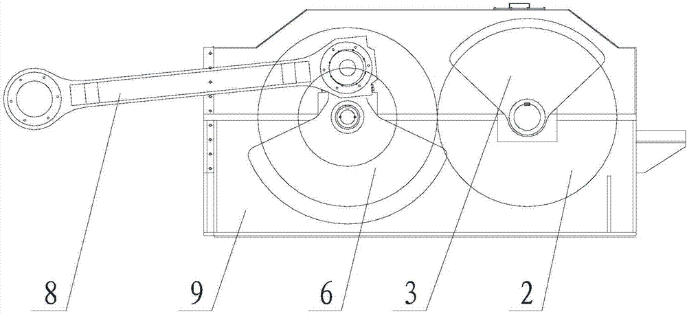
[0023] This embodiment provides a cold-rolled pipe mill transmission device with a mass balance mechanism. The transmission device can effectively offset the inertial force and has high production efficiency. The production cost of the device is low and the production cycle is short. The transmission device is mainly installed on the cold rolling mill and can also be installed on other equipment.

[0024] Such as image 3 and Figure 4 As mentioned above, the transmission device of the cold-rolled pipe mill in this embodiment mainly includes a driving shaft 1, a driving gear 2, a first sector 3, a driven shaft 4, a driven gear 5, a second sector 6, a rotating shaft 7, and a connecting rod 8 and box 9. Wherein the driving shaft 1 and the casing 9 have one, and the driving gear 2, the first sector block 3, the driven shaft 4, the...


PUM


Abstract

The invention discloses a cold-rolling pipe mill transmission device with a mass balance mechanism. The cold-rolling pipe mill transmission device comprises a driving shaft, driving gears, first sector-shaped blocks, driven shafts, driven gears, second sector-shaped blocks, rotary shafts and connecting rods. The two first sector-shaped blocks are mounted on the driving shaft. The middle portions of the second sector-shaped blocks are symmetrically mounted at the opposite ends of the two driven shafts. The two rotary shafts are symmetrically mounted at the ends of the two second sector-shaped blocks. Due to the fact that the two symmetrical driven shafts, the two second sector-shaped blocks and the two rotary shafts form two symmetrical crank throws, an existing crankshaft is replaced with the two crank throws, the production cost is lowered, and the production cycle is shortened; the two crank throws drive the corresponding connecting rods to rotate, the bending force and twisting force generated when the two connecting rods are not synchronous are avoided, and the service life of parts is prolonged; and the first sector-shaped blocks and the second sector-shaped blocks are arranged in a staggered manner, the inertia force can be effectively eliminated, the speed of the cold-rolling pipe mill transmission device is increased, and accordingly the production efficiency is improved.

Description

technical field [0001] The invention relates to a special equipment for processing metal pipes, in particular to a transmission device of a cold-rolled pipe mill with a mass balance mechanism. Background technique [0002] The cold-rolled pipe mills currently used in the market, except for a few large-scale cold-rolled pipe mills, are directly driven by hydraulic cylinders to reciprocate the working frame, and their transmission devices are almost all driven by motors. The transmission structure of the block, that is, the transmission mechanism of the cold rolling mill is driven by the motor through the pulley or the reduction box, or the motor is directly connected with the transmission mechanism of the cold rolling mill through the coupling, and then the transmission mechanism drives the working frame to reciprocate Achieve rolling. [0003] According to the dynamic analysis, during the rolling process, the working frame of the cold rolling mill will generate a large iner...

Claims


Application Information

Patent Timeline
Patent Type & Authority Applications(China)
IPC IPC(8): B21B35/12
CPCB21B35/12Y02P70/10
Inventor 林秀华朱旭
Owner 广东科莱博科技有限公司
Learn More