Endoscope self-locking device and endoscope
A self-locking device and endoscope technology, which is applied in the field of endoscopes, can solve the problem that the rotating handle cannot be self-locked
- Summary
- Abstract
- Description
- Claims
- Application Information
AI Technical Summary
Problems solved by technology
Method used
Image
Examples
Embodiment 1
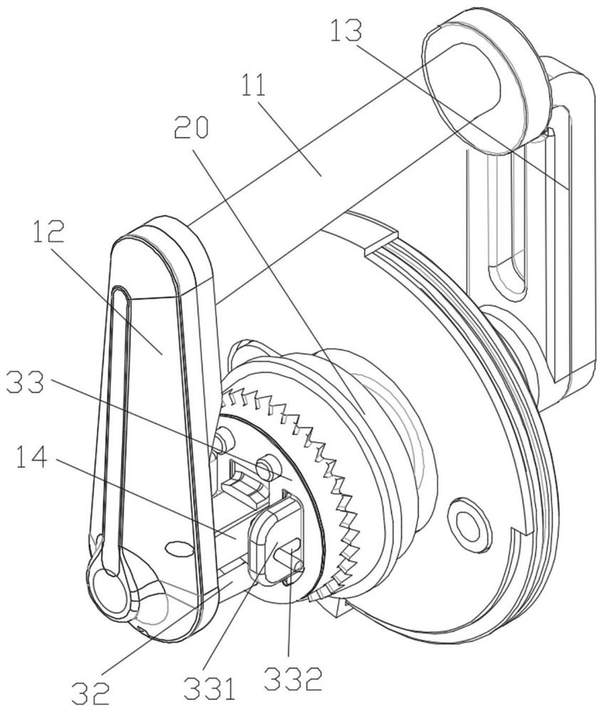
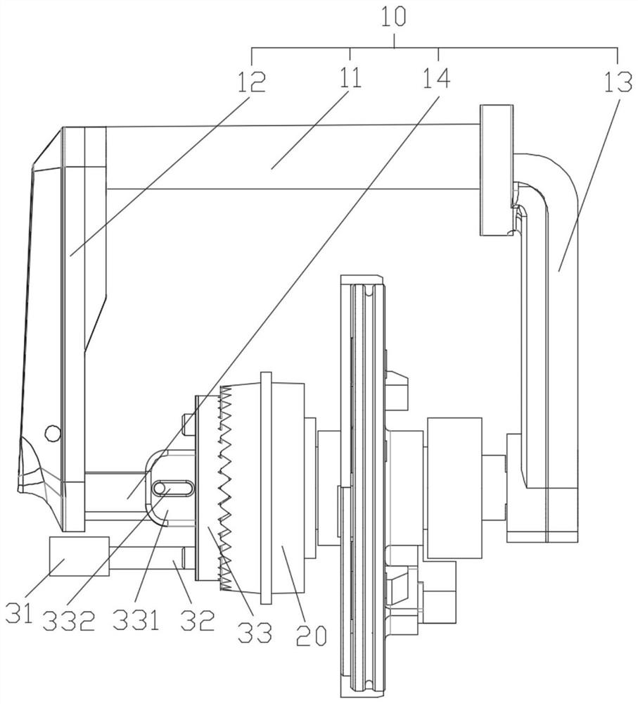
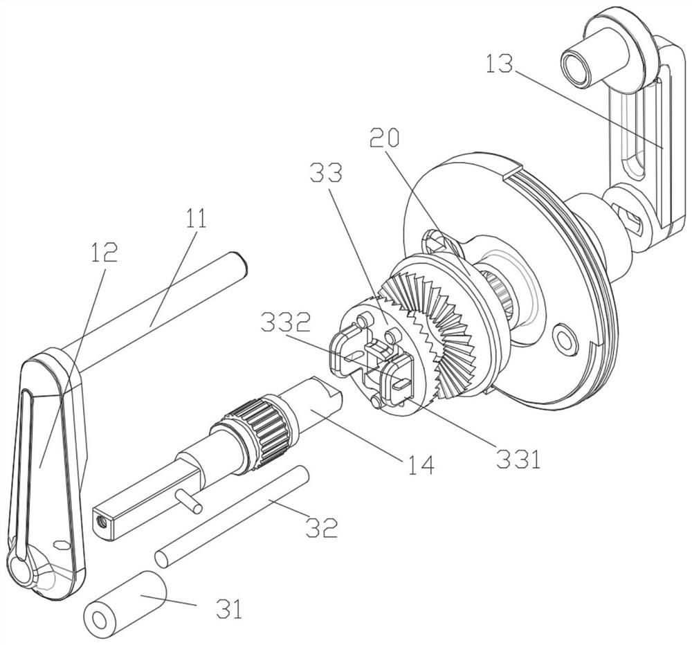
[0041] This embodiment provides an endoscope self-locking device, including a housing and a rotating handle 10, the rotating handle 10 is connected to the housing, and the rotating handle 10 rotates relative to the housing;
[0042] Described rotating handle 10 comprises toggle support 11, left support 12, right support 13 and rotating shaft 14, and described toggle support 11 is fixedly connected with left support 12 and right support 13 respectively, and described left support 12 and right support 13 all connecting the rotating shaft 14, the rotating shaft 14 passes through the housing;
[0043] A locking member 20 is fixedly arranged in the housing, and the locking member 20 is rotatably connected to the rotating shaft 14, and the rotating shaft 14 is movably connected with a locking mechanism 30 for cooperating with the locking member 20;
[0044] The locking mechanism 30 includes a base 31, a push rod 32 and a locking member 2 33, the housing is fixedly connected to the b...
Embodiment 2
[0049] On the basis of Embodiment 1, preferably, the first locking member 20 and the second locking member 33 are engaged through a toothed structure.
[0050]Preferably, both the first locking member 20 and the second locking member 33 are toothed disc structures.
[0051] The teeth of the chainring mesh together and have a larger contact surface, which can achieve a better locking effect.
[0052] The cooperating mode of locking part 1 20 and locking part 2 33 is not limited to tooth structure meshing, other can make locking part 1 20 and locking part 2 33 cooperate, the structure that reaches the purpose of locking all can; A groove is provided on the locking piece 1 20, the outer diameter of the locking piece 2 33 is adapted to the groove, and the locking piece 2 33 falls into the groove, which can also achieve the purpose of the present invention.
Embodiment 3
[0054] On the basis of Embodiment 1 or 2, preferably, the second locking member 33 is provided with a connection block 331, and a connection groove 332 is provided on the connection block 331 along the axial direction of the rotating shaft 14, and the connection block 331 is connected by The slot 332 is slidably connected to the rotating shaft 14 .
[0055] It should be noted that two connecting shafts can be arranged on the rotating shaft 14, and the connecting shafts are connected in the connecting groove 332, and the connecting groove 332 can move relative to the connecting shafts; , so that the connecting groove 332 is relatively fixed to the connecting shaft.
[0056] During use, the push rod 32 pushes the locking part 2 33 to move and cooperate with the locking part 1 20. At this time, the end of the connecting groove 332 away from the locking part 20 slides to the position closest to the locking part 20, and connects with the locking part 1 20. Cooperate with the shaft...
PUM
 Abstract
Description
Claims
Application Information
 - R&D
- Intellectual Property
- Life Sciences
- Materials
- Tech Scout
- Unparalleled Data Quality
- Higher Quality Content
- 60% Fewer Hallucinations
Browse by: Latest US Patents, China's latest patents, Technical Efficacy Thesaurus, Application Domain, Technology Topic, Popular Technical Reports.
© 2025 PatSnap. All rights reserved.Legal|Privacy policy|Modern Slavery Act Transparency Statement|Sitemap|About US| Contact US: help@patsnap.com


