Endoscope self-locking device and endoscope

A self-locking device and endoscope technology, which is applied in the field of endoscopes, can solve the problem that the rotating handle cannot be self-locked

Pending Publication Date: 2020-10-23
HUNAN VATHIN MEDICAL INSTR CO LTD
View PDF0 Cites 3 Cited by
  • Summary
  • Abstract
  • Description
  • Claims
  • Application Information

AI Technical Summary

Problems solved by technology

[0003] The purpose of the present invention is to provide an endoscope self-locking device to solve the technical problem in the ...

Method used


Image

  • Endoscope self-locking device and endoscope
  • Endoscope self-locking device and endoscope
  • Endoscope self-locking device and endoscope

Examples


Embodiment 1

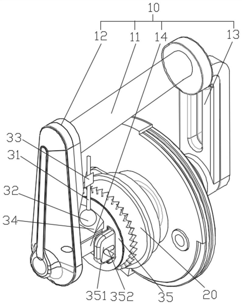
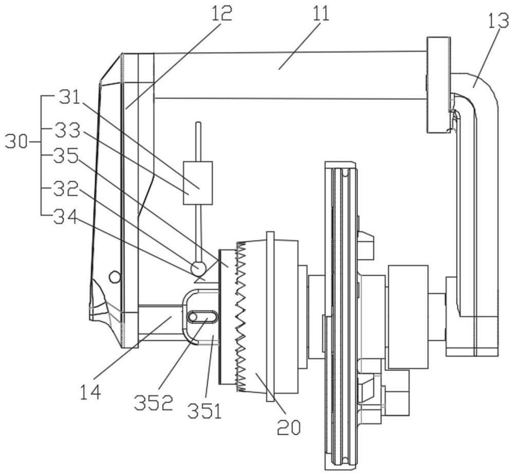
[0036] This embodiment provides an endoscope self-locking device, including a housing and a rotating handle 10, the rotating handle 10 is connected to the housing, and the rotating handle 10 rotates relative to the housing;

[0037] The rotary handle 10 includes a toggle bracket 11, a left bracket 12, a right bracket 13 and a rotating shaft 14, and the toggle bracket 11 is fixedly connected with the left bracket 12 and the right bracket 13 respectively; the rotating shaft 14 passes through the housing respectively Fixedly connected with the left bracket 12 and the right bracket 13;

[0038] A locking member 20 is fixedly arranged in the housing, and the locking member 20 is rotatably connected to the rotating shaft 14, and the rotating shaft 14 is movably connected with a locking mechanism 30 for cooperating with the locking member 20;

[0039] The locking mechanism 30 includes an operating rod 31, a roller 32, a locking member 33, a wedge block 34 and a second locking member ...

Embodiment 2

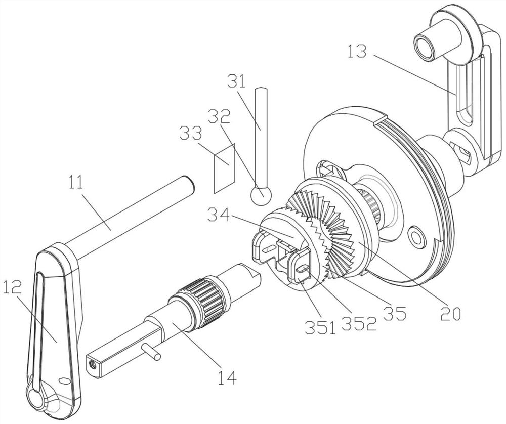
[0045] On the basis of Embodiment 1, preferably, the first locking member 20 and the second locking member 35 are engaged through a toothed structure.

[0046] Preferably, both the first locking member 20 and the second locking member 35 are toothed disc structures.

[0047] The teeth of the chainring mesh together and have a larger contact surface, which can achieve a better locking effect.

[0048] The mode of cooperation between the first locking part 20 and the second locking part 35 is not limited to the engagement of the toothed structure, other structures that can make the first locking part 20 and the second locking part 35 cooperate to achieve the purpose of locking are all available; A groove is provided on the locking piece 1 20, the outer diameter of the locking piece 2 35 is adapted to the groove, and the locking piece 2 35 falls into the groove, which can also achieve the purpose of the present invention.

Embodiment 3

[0050] On the basis of Embodiment 1 or 2, preferably, the second locking member 35 is provided with a connecting block 351, and a connecting groove 352 is provided on the connecting block 351 along the axial direction of the rotating shaft 14, and the connecting block 351 is connected by The slot 352 is slidably connected to the rotating shaft 14 .

[0051]It should be noted that two connecting shafts can be arranged on the rotating shaft 14, and the connecting shafts are connected in the connecting groove 352, and the connecting groove 352 can move relative to the connecting shafts; Make the connecting groove 352 relatively fixed with the connecting shaft.

[0052] The connecting blocks 351 are arranged on both sides of the rotating shaft 14, and the distance between the two connecting blocks 351 is greater than or equal to the diameter of the rotating shaft 14; the best way is that the distance is just suitable for the diameter of the rotating shaft 14, that is, the connecti...


PUM


Abstract

The invention relates to the technical field of endoscopes, in particular to an endoscope self-locking device. The device comprises a shell and a rotating handle, a first locking piece is fixedly arranged in the shell, a rotating shaft is rotatably connected into the first locking piece, and a locking mechanism used for being matched with the first locking piece is movably connected to the rotating shaft; the locking mechanism comprises an operating rod, a rolling wheel, a locking piece, a wedge-shaped block and a second locking piece, the locking piece is connected to the operating rod, the operating rod is matched with the wedge-shaped block, the wedge-shaped block is arranged on the second locking piece, the second locking piece is movably connected to the rotating shaft, and the secondlocking piece can only move in the axial direction of the rotating shaft; and the operating rod controls the second locking piece to be matched with the first locking piece to achieve self-locking, and meanwhile the locking piece locks the operating rod. Self-locking can be achieved by rotating the handle, locking of an insertion tube is achieved, the imaging stability of the insertion tube is guaranteed, and meanwhile the fatigue strength of an operator is reduced.

Description

technical field [0001] The invention relates to the technical field of endoscopes, in particular to an endoscope self-locking device and an endoscope. Background technique [0002] In endoscope products, the bending and turning of the end of the insertion tube is realized by turning the turning handle, but the bending and turning of the insertion tube has a certain resilience. When the user does not apply force to the turning handle during operation, the insertion tube will rebound and deform. ;When observing at a certain angle inside the human body, because the insertion tube should be bent and rotated to keep it at a specific position, the user needs to apply force to the rotating handle all the time; but the user always applies force to control the insertion tube to maintain a specific position , will cause user fatigue, and the stability of the control is poor, so a self-locking structure needs to be provided to keep the insertion tube at a specific position. Contents ...

Claims


Application Information

Patent Timeline
IPC IPC(8): A61B1/005A61B1/00
CPCA61B1/0052A61B1/00147
Inventor 不公告发明人
Owner HUNAN VATHIN MEDICAL INSTR CO LTD
Why Eureka
Try Eureka