
A safety emergency escape device for preventing fire

A safety and equipment technology, applied in the direction of life-saving equipment, building rescue, etc., can solve the problems that affect people's escape, it is difficult to find fixed objects, and preparations require a lot of time

Active Publication Date: 2022-08-09
嘉泰工程技术有限公司
View PDF0 Cites 0 Cited by
  • Summary
  • Abstract
  • Description
  • Claims
  • Application Information

AI Technical Summary

Problems solved by technology

[0003] When people encounter a fire on a high-rise building and the door is blocked, they usually tie the rope to a fixed object, and then climb to the ground along the rope from the corridor. When a fire occurs, the situation is urgent, and there is a lot of smoke in the room. It may be difficult to find a fixed object in a short period of time, and the preparation work will take a lot of time, which will affect people's escape. Secondly, it will be troublesome for people to climb down the corridor, and accidents will happen if they are not careful

Method used


Image

  • A safety emergency escape device for preventing fire
  • A safety emergency escape device for preventing fire
  • A safety emergency escape device for preventing fire

Examples


Embodiment approach 1

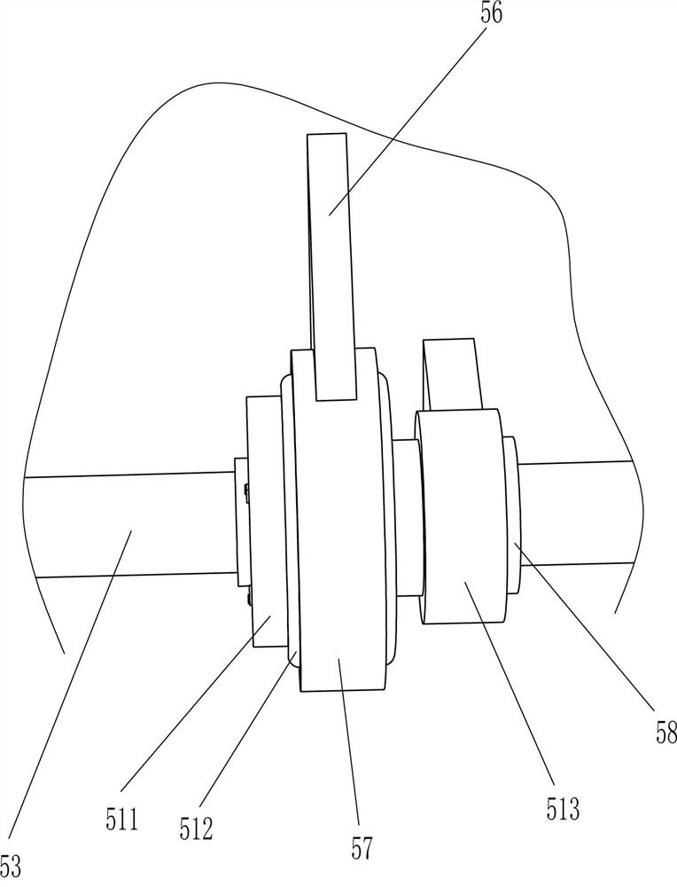
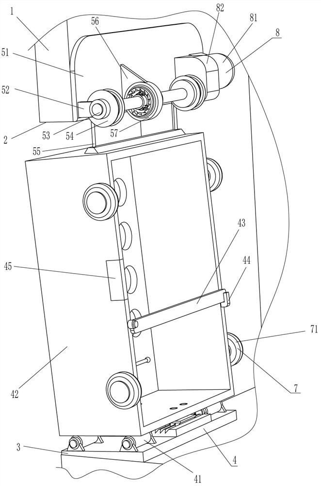
[0024] A safety emergency escape device for preventing fire, such as Figure 1-3 As shown, it includes a support plate 3, a man-carrying mechanism 4 and a deceleration mechanism 5, a mounting groove 2 is opened on the wall 1, a support plate 3 is connected to the bottom of the mounting groove 2, and a man-carrying mechanism 4 is installed on the support plate 3, A deceleration mechanism 5 is installed on the wall body 1 .

[0025] The man-carrying mechanism 4 includes a support roller 41, a man-carrying box 42, a protective plate 43, a limit card 44 and a magnet 45. Two support rollers 41 and four support rollers 41 are installed on the front and rear sides of the top of the support plate 3 through bolts. There is a manned box 42 on it, the support roller 41 is in contact with the manned box 42, the right front part of the manned box 42 is hingedly connected with a protective plate 43, the right rear of the passenger box 42 is connected with a limit card 44, and the protective...

Embodiment approach 2

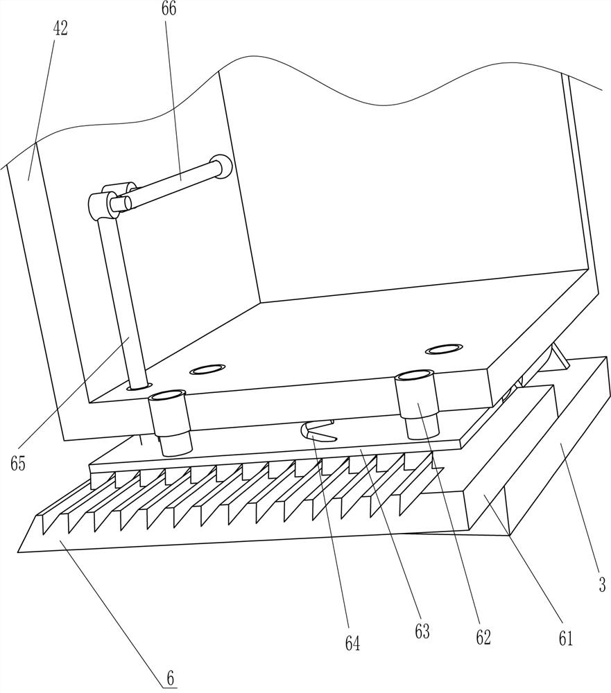
[0031] On the basis of Embodiment 1, as figure 1 and Figure 4As shown, a locking mechanism 6 is also included. The locking mechanism 6 includes a first toothed plate 61, a telescopic sleeve 62, a second toothed plate 63, a second elastic piece 64, a pull rod 65 and a crowbar 66. The top of the support plate 3 is connected with a first toothed plate 61. A toothed plate 61 , two telescopic sleeves 62 are connected on the front and rear sides of the bottom of the manned box 42 , and a second toothed plate 63 is connected between the bottom ends of the four telescopic sleeves 62 . The second toothed plate 63 is connected to the first toothed plate 61 Meshing, a second elastic piece 64 is connected between the second toothed plate 63 and the bottom of the manned box 42, a pull rod 65 is connected to the left side of the top of the second toothed plate 63, the pull rod 65 slides through the bottom of the manned box 42, and the top of the pull rod 65 rotates A crowbar 66 is connect...


PUM


Abstract

The invention relates to an emergency escape device, in particular to a safety emergency escape device for preventing fire. Technical problem to be solved: to provide a safety emergency escape device that can help people escape quickly and ensure people's safety to prevent fire. The technical scheme is: a safety emergency escape device for preventing fire, comprising a support plate, a mounting groove is formed on the wall, and the support plate is fixed on the inner wall of the mounting groove; a man-carrying mechanism, the man-carrying mechanism Installed on the support plate, the man-carrying mechanism is used to send people to the ground. The present invention can safely send people to the ground through the manned mechanism, which can effectively help people to escape quickly and ensure people's safety. Collision; the manned box can be stuck by the locking mechanism to prevent the passenger box from accidentally slipping out.

Description

technical field [0001] The invention relates to an emergency escape device, in particular to a safety emergency escape device for preventing fire. Background technique [0002] Fire refers to the disaster caused by uncontrolled combustion in time or space. Among various disasters, fire is one of the most frequent and common disasters that threaten public safety and social development. Summarize the law of fire occurrence, reduce the fire and its harm to human as much as possible, when a fire occurs, people need to escape as soon as possible. [0003] When people encounter a fire on a high-rise building and the door is blocked, they usually tie the rope to a fixed object, and then climb the rope from the corridor to the ground. It may be difficult to find a fixed object in a short period of time, and the preparation work requires a lot of time, which affects people's escape. Secondly, it is also very troublesome for people to climb down from the corridor, and accidents will ...

Claims


Application Information

Patent Timeline
Patent Type & Authority Patents(China)
IPC IPC(8): A62B1/02
CPCA62B1/02
Inventor 黄沪秀
Owner 嘉泰工程技术有限公司
Learn More