Multidirectional aeration device for sewage treatment

A sewage treatment and aeration device technology, applied in water/sewage treatment, water/sewage treatment equipment, water aeration, etc., can solve problems such as the influence of aeration effect and single aeration method

Inactive Publication Date: 2020-10-23
庞俊平
View PDF0 Cites 4 Cited by
  • Summary
  • Abstract
  • Description
  • Claims
  • Application Information

AI Technical Summary

Problems solved by technology

[0003] Aeration is a commonly used method in sewage treatment. The existing aeration devices generally use fixed-installed aeration pipelines to perform aeration in a fixed direction. This aeration method is relatively simple and the aeration effect is also affected.

Method used


Image

  • Multidirectional aeration device for sewage treatment
  • Multidirectional aeration device for sewage treatment
  • Multidirectional aeration device for sewage treatment

Examples


Embodiment 1

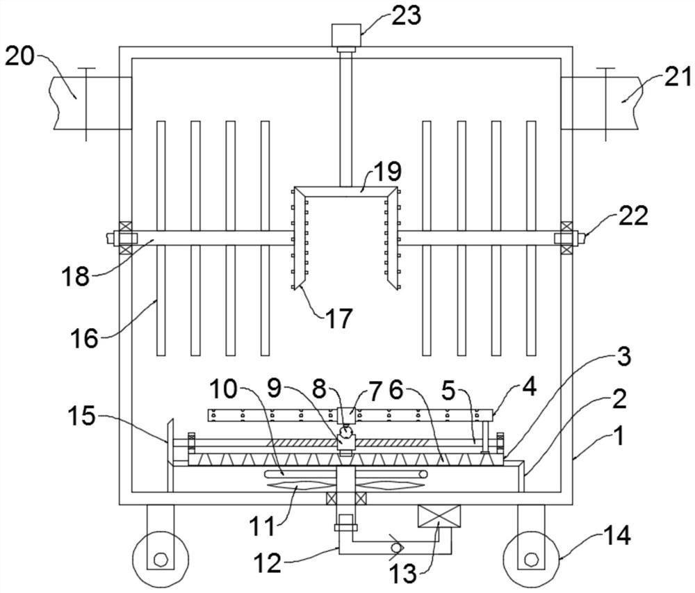
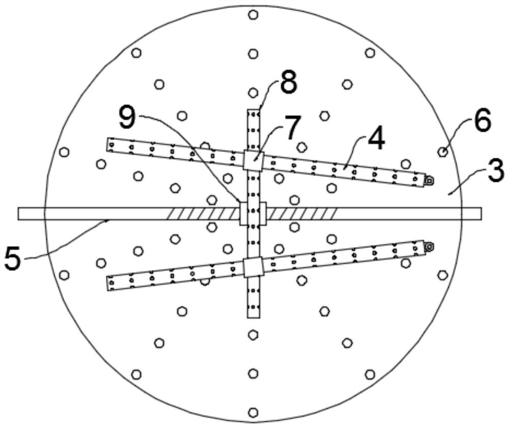
[0024] see Figure 1~3 , in an embodiment of the present invention, a multi-directional aeration device for sewage treatment includes a box body 1 and an aeration unit, and the bottom of the box body 1 is evenly and symmetrically fixed with rollers 14 to facilitate the movement of the device. The water inlet pipe 20 and the water outlet pipe 21 are connected, and valves are installed on the water inlet pipe 20 and the water outlet pipe 21. The aeration unit includes a mounting plate 3, a reciprocating screw rod 5, an internal thread sleeve 9, a first aeration pipe 8, The sliding sleeve 7, the second aeration pipe 4 and the arc-shaped air jet pipe 10, the installation plate 3 is arranged at the lower part of the inner cavity of the box body 1 and an installation shaft is fixed in the middle of the bottom, and the bottom end of the installation shaft runs through the bottom of the box body 1 and extends to Below the box body 1, the bottom end of the installation shaft penetrates...

Embodiment 2

[0028] see Figure 4 The difference between this embodiment of the present invention and Embodiment 1 is that a screw rod 24 is fixed at the bottom of the third bevel gear 19, and a second through hole is opened on the screw rod 24, and the size of both ends of the second through hole is larger than the middle size, When the screw rod 24 rotates, the sewage passes through the second through hole, and the change of flow velocity further disturbs the flow and generates air bubbles, which improves the aeration efficiency.

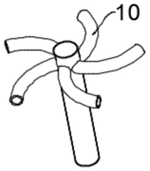
[0029]The working principle of the present invention is: when working, the first air supply pipe 12 supplies air to the installation shaft and then sprays out from the arc-shaped air injection pipe 10, and drives the installation shaft and the installation plate 3 to rotate under the reaction force, and the installation plate 3 drives it to reciprocate The screw rod 5, the first aeration pipe 8 and the second aeration pipe 4 revolve around to perform rotary ae...


PUM


Abstract

The invention discloses a multidirectional aeration device for sewage treatment, relates to the technical field of water treatment equipment, and mainly aims to solve the problem of single aeration mode in the prior art. The multidirectional aeration device comprises a box body and an aeration unit; the aeration unit comprises a mounting plate, a reciprocating screw rod, an internal thread sleeve,a first aeration pipe, a sliding sleeve, a second aeration pipe and an arc-shaped gas ejector pipe; a stirring unit is also arranged at a part, above the aeration unit, in the box body; the stirringunit comprises a motor, second bevel gears, a third bevel gear, a rotating shaft and a stirring rod; an aeration unit is arranged, a first aeration pipe and a second aeration pipe are arranged for revolution and rotary aeration, the aeration range is large, the effect is good, the first aeration pipe is driven to reciprocate through cooperation, meanwhile, the second aeration pipe is driven to swing, the aeration angle of the second aeration pipe is continuously changed, the aeration range and direction are further expanded, and the aeration efficiency is further improved; the stirring unit isarranged, the two second bevel gears rotate reversely for aeration during stirring, rotary impact is formed, and the aeration effect is better.

Description

technical field [0001] The invention relates to the technical field of water treatment equipment, in particular to a multi-directional aeration device for sewage treatment. Background technique [0002] Water treatment methods include physical treatment and chemical treatment. Human beings have used water treatment methods for many years. Physical methods include the use of various filter materials with different pore sizes, and use adsorption or barrier methods to exclude impurities in water. Physical methods also include precipitation methods. Chemical methods use Various chemicals convert impurities in water into substances that are less harmful to the human body, or concentrate impurities in water. After the impurities in water gather, the volume becomes larger, and the impurities can be removed by filtration. [0003] Aeration is a commonly used method in sewage treatment. The existing aeration devices generally use fixedly installed aeration pipelines to perform aerat...

Claims


Application Information

Patent Timeline
Patent Type & Authority Applications(China)
IPC IPC(8): C02F7/00
CPCC02F7/00C02F2201/002Y02W10/10
Inventor 庞俊平
Owner 庞俊平
Why Eureka
Try Eureka