Non-woven fabric spunlace machine and working principle thereof

A technology of non-woven fabrics and spunlace machines, which is applied in the directions of needle punching machines, non-woven fabrics, textiles and paper making, etc., can solve the problems affecting the durability and stability of spunlace devices, poor spunlace effect, and increasing the burden on water pumps, etc. question

Active Publication Date: 2020-10-23
南通通州江华纺织有限公司
View PDF8 Cites 4 Cited by
  • Summary
  • Abstract
  • Description
  • Claims
  • Application Information

AI Technical Summary

Problems solved by technology

[0002] In the field of textile technology, the spunlace method relies on the water needles formed by spraying a very fine high-pressure water flow from the spunlace head to spunlace the non-woven fabric web, and the fibers in the non-woven fabric web are entangled and fixed on each other. Together, to achieve the purpose of strengthening the non-woven fabric, it is obvious that the spunlace head is the key component of the spunlace method. During the use of the traditional non-woven spunlace mechanism, the non-woven fiber web will cause the non-woven fiber to The position of the net moves, and the spunlace effect is poor. At the same time, the existing non-woven spunlace device is usually directly injected into a high-pressure water source, which increases the burden on the water pump, thus affecting the durability and stability of the entire spunlace device.

Method used


Image

  • Non-woven fabric spunlace machine and working principle thereof
  • Non-woven fabric spunlace machine and working principle thereof

Examples


Embodiment Construction

[0020] The present invention will be further described below in conjunction with the accompanying drawings.

[0021] In order to make the object, technical solution and advantages of the present invention clearer, the present invention will be further described in detail below in conjunction with the accompanying drawings and specific embodiments. It should be understood that the specific embodiments described here are only used to explain the present invention, and are not intended to limit the present invention.

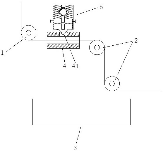
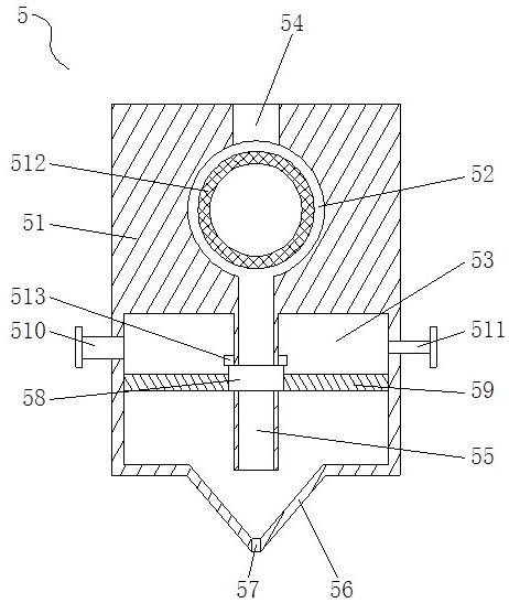
[0022] see Figure 1-2 , a non-woven spunlace machine, including a feed roller 1, a discharge roller 2 and a water collection box 3, and also includes a spunlace board 4 and a spunlace head 5, the spunlace board 4 is a hollow structure, and the left and right ends are arranged The opening, the feed roller 1 and the discharge roller 2 are respectively located on the left and right sides of the spunlace board, and the water collection tank 3 is located below the spu...


PUM


Abstract

The invention discloses a non-woven fabric spunlace machine and a working principle thereof. The non-woven fabric spunlace machine comprises a feeding roller, a discharging roller and a water collecting tank and further comprises a spunlace plate and a spunlace head; the spunlace plate is of a hollow structure, openings are formed in the left end and the right end of the spunlace plate, the feeding roller and the discharging roller are respectively positioned on the left side and the right side of the spunlace plate, and the water collecting tank is positioned below the spunlace plate and thedischarging roller; the upper end of the spunlace plate is provided with a through hole, and the lower end of the spunlace head extends into the through hole and is vertical to the spunlace plate; andthe spunlace head includes a base, an upper water cavity and a lower water cavity are formed inside the base, a water inlet is arranged at the top of the upper water cavity while the lower end of theupper water cavity is provided with a plurality of water outlet pipes, the water outlet pipes extend into the lower water cavity, a hydro-acupuncture plate is arranged at the bottom of the lower water cavity, a plurality of hydro-acupuncture holes are formed at the bottom of the hydro-acupuncture plate, and a press plate is slidably arranged outside the water outlet pipes. According to the non-woven fabric spunlace machine and the working principle thereof, the spunlace plate of the hollow structure with the openings at two ends is used, so that a non-woven fabric fiber web is subjected to spunlace in the spunlace plate, the movement of the non-woven fabric fiber web caused by spunlace pressure is avoided, and the spunlace effect is ensured.

Description

technical field [0001] The invention relates to the technical field of non-woven fabrics, in particular to a non-woven fabric spunlace machine and its working principle. Background technique [0002] In the field of textile technology, the spunlace method relies on the water needles formed by spraying a very fine high-pressure water flow from the spunlace head to spunlace the non-woven fabric web, and the fibers in the non-woven fabric web are entangled and fixed on each other. Together, to achieve the purpose of strengthening the non-woven fabric, it is obvious that the spunlace head is the key component of the spunlace method. During the use of the traditional non-woven spunlace mechanism, the non-woven fiber web will cause the non-woven fiber to The position of the net moves, and the spunlace effect is poor. At the same time, the existing non-woven spunlace device is usually directly injected into a high-pressure water source, which increases the burden on the water pump,...

Claims


Application Information

Patent Timeline
Patent Type & Authority Applications(China)
IPC IPC(8): D04H18/04
CPCD04H18/04Y02W30/66
Inventor 胡小龙朱晨萍徐晓禹黄丽华崇庆成张玉梅
Owner 南通通州江华纺织有限公司
Why Eureka
Try Eureka