
Anti-theft door lock

An anti-theft door lock and lock body technology, which is applied in building locks, buildings, building structures, etc., can solve the problems that affect the daily life of users, the key is difficult to insert, and the door is difficult to open.

Active Publication Date: 2020-10-23
山东依蒙智能科技有限公司
View PDF6 Cites 0 Cited by
  • Summary
  • Abstract
  • Description
  • Claims
  • Application Information

AI Technical Summary

Problems solved by technology

[0003] There are also some technical solutions about anti-theft door locks in the prior art, such as a Chinese patent with application number 2015103227454, which discloses an anti-theft door lock, including a lock housing, a main bolt assembly, an oblique bolt assembly, a lock Tongue dial assembly, deadbolt dial control assembly, oblique bolt single control, oblique tongue extension control assembly, oblique tongue retraction control assembly, deadbolt dial sleeve one-way control I, deadbolt dial sleeve one-way control II, deadbolt dial Sleeve return component I and deadbolt dial sleeve return assembly II, the deadbolt dial control component is on the lock shell in the opposite direction to the lock tongue; the lock cylinder invented by this patent is hidden inside the door body, and it is possible for illegal personnel to unlock it with technology The method of stealing increases the difficulty and improves the security, but it still needs to insert the key to open it, and for the elderly with inflexible hands, especially for people with Parkinson's disease, due to the shaking of the hand when unlocking It is easy to cause the key to be difficult to insert into the lock hole, making it difficult to open the door, thus affecting the daily life of the user

Method used


Image

  • Anti-theft door lock
  • Anti-theft door lock
  • Anti-theft door lock

Examples


Embodiment Construction

[0023] In order to make the technical means, creative features, goals and effects achieved by the present invention easy to understand, the present invention will be further described below in conjunction with specific embodiments.

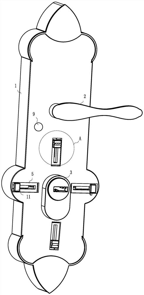
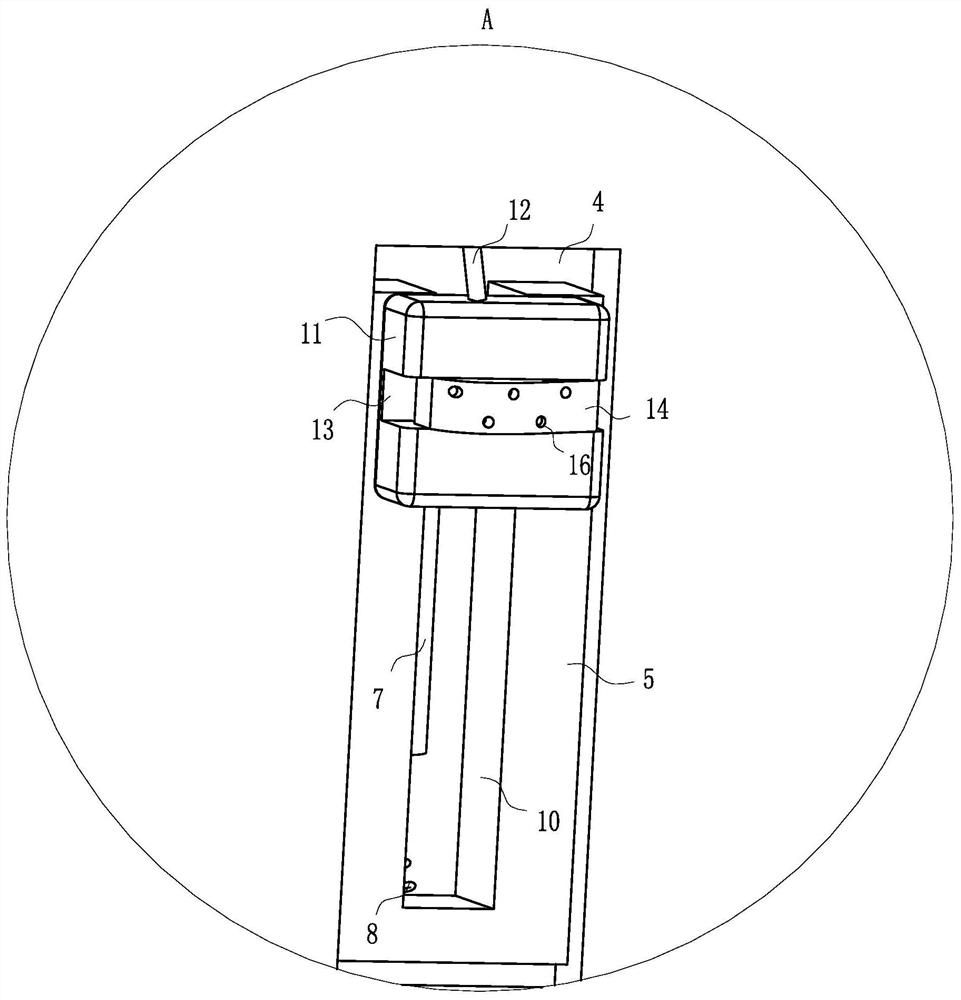
[0024] Such as Figure 1 to Figure 6 As shown, an anti-theft door lock according to the present invention includes a lock body, and the lock body includes a housing 1, a handle 2 and a lock head 3. Four rectangular through-holes 4, a splint 5 is installed in rotation at the rectangular through-hole 4, the end of the splint 5 close to the lock head 3 is made of iron material, the splint 5 is located in the inner cavity of the housing 1, and the shell Body 1 inner cavity is positioned at rectangular through hole 4 and fixes limit block 6, and described limit block 6 side wall is provided with electromagnet 7, and the output end of described electromagnet 7 is fixed with return spring 8, and described return spring 8 The end away from the correspond...


PUM


Abstract

The invention belongs to the technical field of anti-theft door locks, and particularly relates to an anti-theft door lock. The anti-theft door lock comprises a lock body, wherein the lock body comprises a shell, a handle and a lock head, four rectangular through holes are formed in the front surface of the shell at equal intervals in the circumferential direction of the lock head, clamping platesare rotationally installed at the rectangular through holes, the ends, close to the lock head, of the clamping plates are made of iron materials, the clamping plates are located in an inner cavity ofthe shell, limiting blocks are fixed at the positions, located at the rectangular through holes, of the inner cavity of the shell, electromagnets are arranged on the side walls of the limiting blocks, reset springs are fixed at the output ends of the electromagnets, and the ends, far away from the corresponding electromagnets, of the reset springs are fixed at the ends, close to the lock head, ofthe adjacent clamping plates. According to the anti-theft door lock, the clamping plates in the four directions are popped up to limit and guide a key on the hand of a user, so that the key on the hand of the user is kept at a correct angle and position, then the user can conveniently align the key, then the door opening efficiency of the user is improved, and convenience is brought to the dailylife of the user.

Description

technical field [0001] The invention belongs to the technical field of anti-theft door locks, in particular to an anti-theft door lock. Background technique [0002] A door lock is a device used to lock the door to prevent others from opening the door. This device may be mechanical or electric, and electric power requires electric energy. There are many types of door locks, and the requirements for door locks are different in various occasions. Ordinary families generally use anti-theft door locks, which are highly secure and relatively cheap; in some high-end places, security agencies will use combination locks and fingerprint locks. Very high and expensive; glass doors are used in many public places, so glass door locks will be more widely used. [0003] There are also some technical solutions about anti-theft door locks in the prior art, such as a Chinese patent with application number 2015103227454, which discloses an anti-theft door lock, including a lock housing, a ma...

Claims


Application Information

Patent Timeline
IPC IPC(8): E05B15/08E05B17/22
CPCE05B15/08E05B17/22
Inventor 董俊彬陶俊李伟
Owner 山东依蒙智能科技有限公司
Learn More