Slow-closing type check valve with low flow resistance

A slow-closing, check valve technology, applied to valve details, control valves, valve devices, etc., can solve problems such as large shock waves, noise, and water hammer effects

Inactive Publication Date: 2020-10-23
HARBIN HBC VALVE
View PDF7 Cites 2 Cited by
  • Summary
  • Abstract
  • Description
  • Claims
  • Application Information

AI Technical Summary

Problems solved by technology

[0005] The purpose of the present invention is to solve the problem of severe water hammer effect an...

Method used


Image

  • Slow-closing type check valve with low flow resistance
  • Slow-closing type check valve with low flow resistance
  • Slow-closing type check valve with low flow resistance

Examples


specific Embodiment approach 1

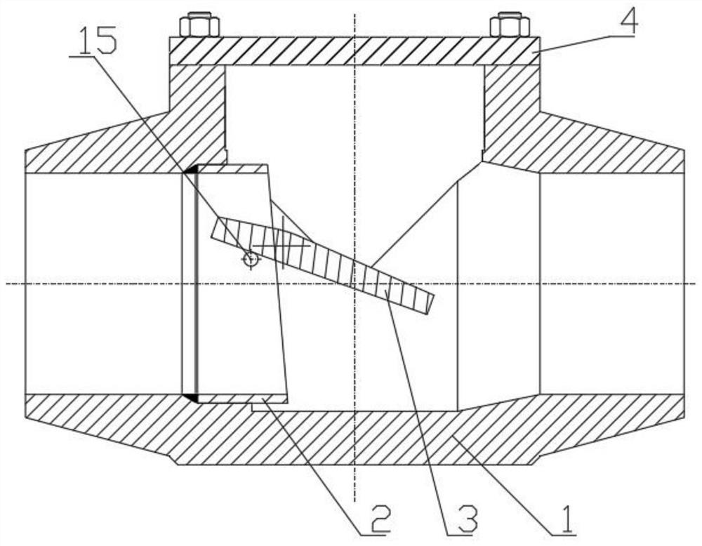
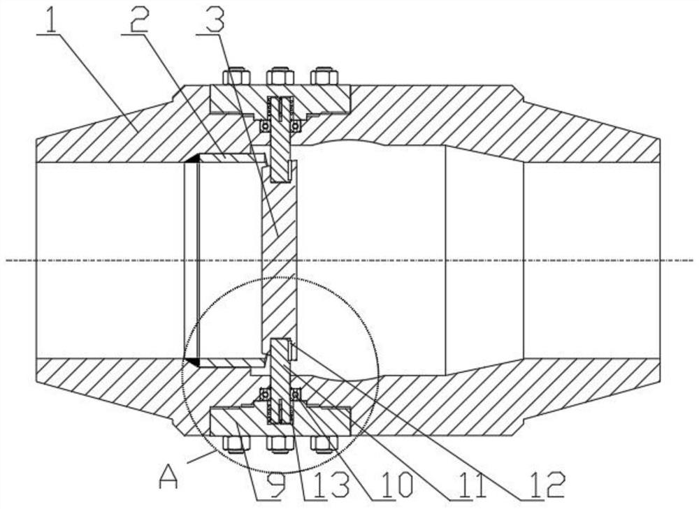
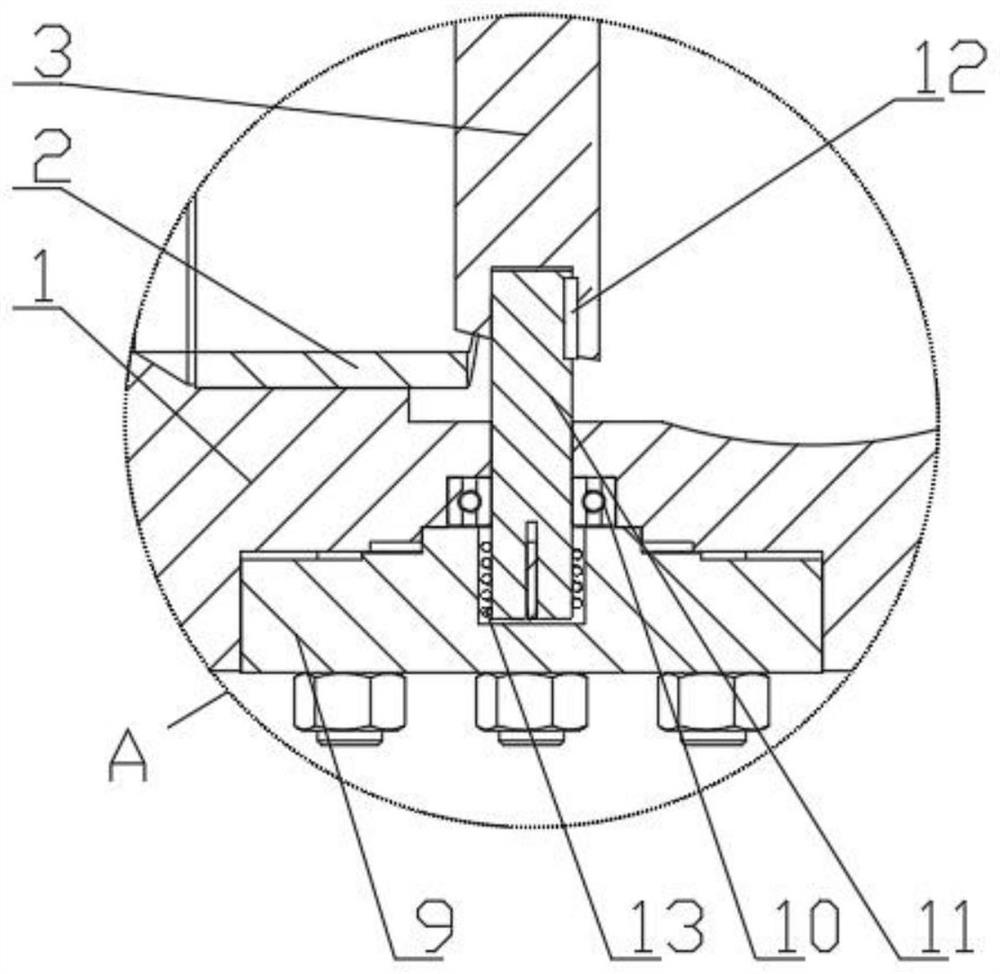
[0026] Specific implementation mode one: combine Figure 1-Figure 4 Describe this embodiment, a slow-closing check valve with low flow resistance in this embodiment, including a valve body 1, a valve seat 2, a valve flap 3, an end cover 9, a rotating shaft 11 and a torsion spring 13, the inlet of the valve body 1 A valve seat 2 is installed on the side, and an end cover 9 is installed on the side of the valve body 1. One end of the torsion spring 13 is connected to the shaft end of the rotating shaft 11, and the other end of the torsion spring 13 is connected to the end cover 9. The valve body 1 is connected, and the torsion spring 13 prevents the valve clack from beating the sealing surface, thereby affecting the sealing performance.

specific Embodiment approach 2

[0027] Specific implementation mode two: Combining figure- Figure 4 Describe this embodiment. A slow-closing check valve with low flow resistance in this embodiment also includes a bearing 10 and a key 12. The rotating shaft 11 is connected to the valve body 1 through the bearing 10. The rotating shaft 11 is eccentric to the disc 3 through the key 12. The positions are connected, and when the medium flows backward, because the upstream and downstream areas of the valve disc 3 located on the rotating shaft 11 are different, the medium pushes the valve disc 3 to generate a closing rotational moment.

specific Embodiment approach 3

[0028] Specific implementation mode three: combination Figure 1-Figure 4 This embodiment is described. In the low flow resistance slow-closing check valve of this embodiment, there are two end caps 9 , and the two end caps 9 are symmetrically installed on both sides of the valve body 1 .


PUM


Abstract

The invention relates to a check valve, belongs to the technical field of valves, and aims to solve the problem in the prior art that when a check valve is opened and closed under a small flow rate, aserious water hammer effect is generated to cause large impact wave and noise. A slow-closing type check valve with low flow resistance comprises a valve body, a valve seat, a valve clack, an end cover, a rotary shaft and a torsional spring; the valve seat is mounted on the inlet side of the interior of the valve body; the end cover is mounted on the side face of the valve body; on end of the torsional spring is connected with the shaft end of the rotary shaft; the other end of the torsional spring is connected with the end cover; and the valve clack is connected with the valve body through the rotary shaft. When a medium flows reversely, the upper and lower incident flow areas of the valve clack on the rotary shaft are different, the medium pushes the valve clack to generate closing rotary torque, the valve clack starts closing, at the same time, the torsional spring is driven to start torsion reversely as the closing force of the valve clack becomes larger and larger, the medium closing force is counteracted through increased torsional torque, and the valve clack is slowly closed, so that the water hammer effect is effectively eliminated, and generation of the impact wave and noise is avoided.

Description

technical field [0001] The invention relates to a check valve and belongs to the technical field of valves. Background technique [0002] Check valve refers to a valve that actively opens and closes the valve disc based on the activity of the medium itself, and is used to prevent the backflow of the medium. It is also called check valve, one-way valve, reverse flow valve and back pressure valve. Its main effect is to prevent media backflow. [0003] Existing check valves generally adopt disc lifting type or disc swinging type directly. The minimum opening force is large during operation. Stable, the valve disc often has the problem of beating the sealing surface. At the same time, when the valve returns to the seat, the non-axial medium cut-off will produce a serious water hammer effect, which will generate a large shock wave and noise in the front-end pipeline, causing the pipeline to vibrate, and even the pipeline. rupture. [0004] Therefore, there is an urgent need to...

Claims


Application Information

Patent Timeline
IPC IPC(8): F16K15/03F16K47/02
CPCF16K15/033F16K47/023
Inventor 赵宇
Owner HARBIN HBC VALVE
Why Eureka
Try Eureka