Pipeline blocking device

A plugging device and pipeline technology, which is applied in the direction of pipe components, pipes/pipe joints/fittings, mechanical equipment, etc., can solve problems that affect the reliability of plugging, such as operational safety, difficulty, heavy workload, and loose plugging

Active Publication Date: 2020-10-23
北京天兴燃气工程有限公司
View PDF6 Cites 5 Cited by
  • Summary
  • Abstract
  • Description
  • Claims
  • Application Information

AI Technical Summary

Problems solved by technology

At present, the plugging machine used in this field mainly uses the expansion cylinder to seal the pipeline, which has the following problems in practical application: 1. The pipeline must be provided with equal-diameter holes, that is, the pipeline is completely cut off, otherwise the expansion cylinder cannot be used to seal; 2. The difficulty and workload of opening equal-diameter holes is relatively large, which affects the operation efficiency; 3. The expansion cylinder requires a high degree of matching of equal-diameter holes, and frequent sealing is not tight, which affects the reliability of sealing and job safety

Method used


Image

  • Pipeline blocking device
  • Pipeline blocking device
  • Pipeline blocking device

Examples


Embodiment Construction

[0039] First of all, it needs to be explained that the orientation words such as up, down, left, right, front, and back described in the present invention are only described according to the accompanying drawings, so as to be easy to understand, and are not intended to limit the technical solution and scope of protection of the present invention. .

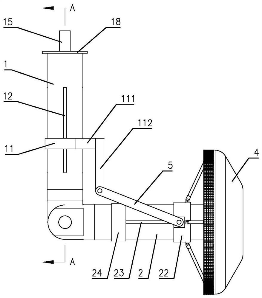
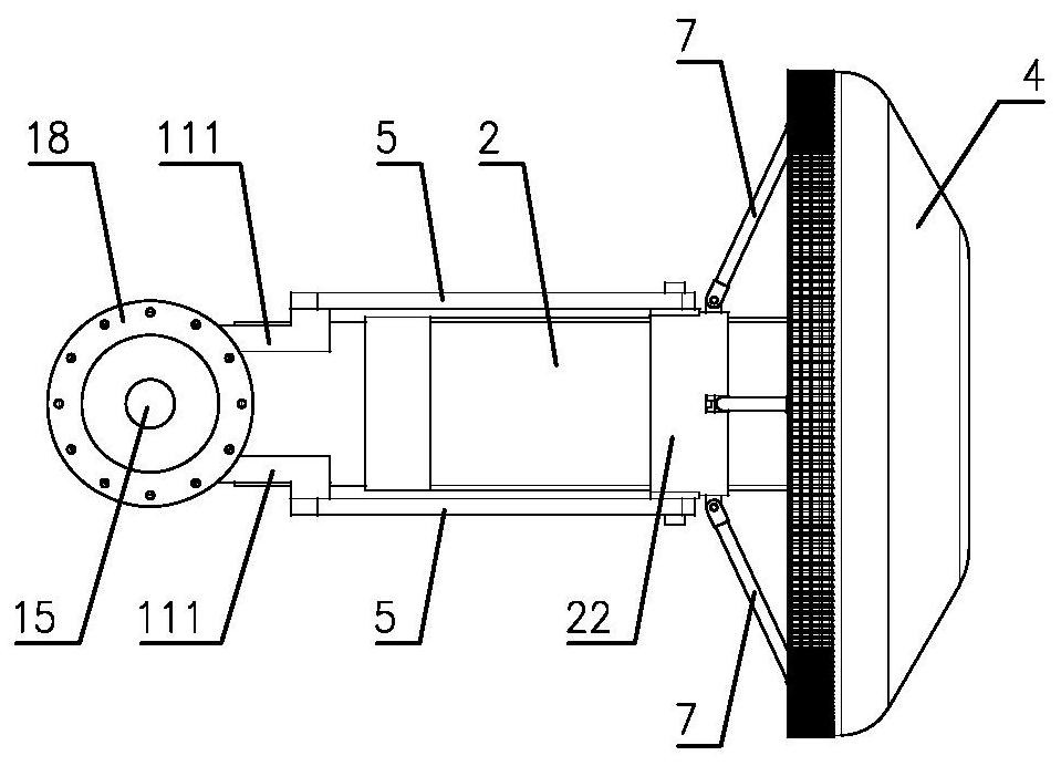
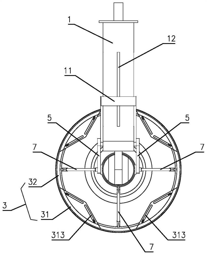
[0040] Such as Figure 1 to Figure 25 Shown is a specific embodiment of a pipeline sealing device of the present invention, including a first support rod 1 , a second support rod 2 , an expansion ring 3 and a sealing cover 4 . The lower end of the first support rod 1 is hinged with the left end of the second support rod 2, the drive ring 11 is sleeved on the first support rod 1, and two front and back symmetrically distributed supports 111 are arranged on the right side of the drive ring 11. The end portion of 111 is provided with downward pulling rod 112 . The right end of the second support rod 2 is provided with a fixed ring 21...


PUM


Abstract

The invention relates to a pipeline blocking device which comprises a first supporting rod, a second supporting rod, an expansion ring and a sealing cover. The first supporting rod is hinged to the second supporting rod. A drive ring, a support and a pull rod are arranged on the first supporting rod. A fixing ring and a sliding ring are arranged on the second supporting rod, and the sliding ring is connected with the pull rod through a transmission rod. The expansion ring comprises first arc parts and second arc parts, wherein the first arc parts and the second arc parts are distributed alternately. Symmetric guide faces are arranged on guide parts of the first arc parts, and sliding grooves and guide holes are formed in the guide faces. The guide holes in the adjacent first arc parts forma splay shape, and supporting lugs are arranged on the second arc parts. The supporting lugs are correspondingly hinged to the fixing ring and the sliding ring through first connecting rods and second connecting rods. Sliding blocks located in the sliding grooves are arranged at the two ends of the second arc parts, and guide pillars located in the guide holes are arranged on the two sides of thesliding blocks. The sealing cover is arranged on the expansion ring in a sleeving manner from right to left and is fixedly connected with the first arc parts. The pipeline blocking device has the beneficial effects that the structure is simple, control is convenient, adaptability is high, and blocking is reliable.

Description

technical field [0001] The invention relates to a sealing device, in particular to a pipeline sealing device used for gas pipeline opening and sealing operations. Background technique [0002] In the process of connection, cutting and rerouting of the gas pipeline network, it is often necessary to perform hole sealing operations. At present, the plugging machine used in this field mainly uses the expansion cylinder to seal the pipeline, which has the following problems in practical application: 1. The pipeline must be provided with equal-diameter holes, that is, the pipeline is completely cut off, otherwise the expansion cylinder cannot be used to seal; 2. The difficulty and workload of opening equal-diameter holes is relatively large, which affects the operation efficiency; 3. The expansion cylinder requires a high degree of matching of equal-diameter holes, and frequent sealing is not tight, which affects the reliability of sealing and job security. Contents of the inve...

Claims


Application Information

Patent Timeline
Patent Type & Authority Applications(China)
IPC IPC(8): F16L55/162
CPCF16L55/1612F16L55/162
Inventor 贾应辉史福海张宗一张建新苏琪郭磊杰张运
Owner 北京天兴燃气工程有限公司
Why Eureka
Try Eureka