
Tripping system of circuit breaker

A circuit breaker and tripping technology, which is applied in the field of tripping systems, can solve problems such as complex assembly process, lack of thermal tripping components, and long tripping time

Pending Publication Date: 2020-10-23
上海瑞忒尔电气技术有限公司
View PDF1 Cites 0 Cited by
  • Summary
  • Abstract
  • Description
  • Claims
  • Application Information

AI Technical Summary

Problems solved by technology

[0004] The purpose of the present invention is to provide a tripping system for a circuit breaker that simplifies the tripping process and aims at the technical defects of the above-mentioned plug-in circuit breaker tripping device lacking thermal tripping elements, many parts, complicated assembly process, and long tripping time. The structure of the system reduces the difficulty of assembly. At the same time, the energy storage element is used to increase the speed at which the moving armature hits the lock, shortens the tripping time, and increases the safety of the circuit breaker.

Method used


Image

  • Tripping system of circuit breaker
  • Tripping system of circuit breaker
  • Tripping system of circuit breaker

Examples


Embodiment 1

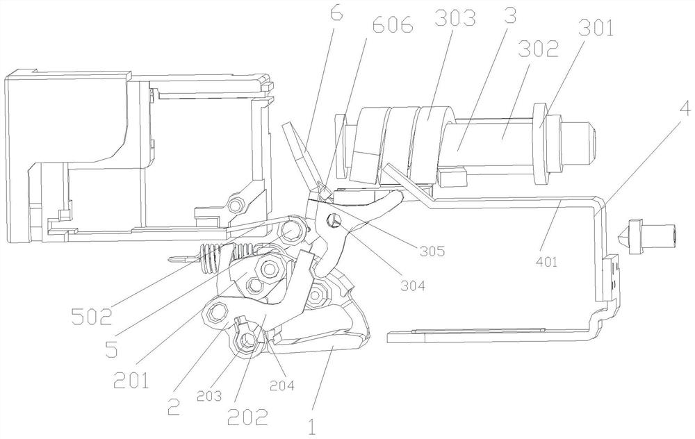
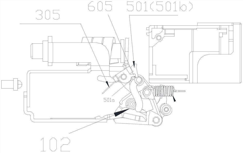
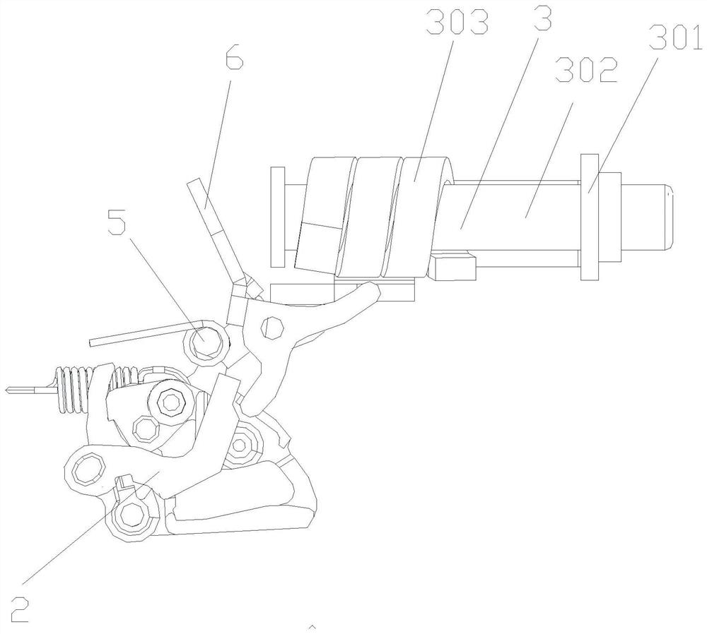
[0045] as attached figure 1and 2 As shown, a tripping system of a circuit breaker provided by this embodiment includes a contact support 1, and a tripping actuator 2 is mounted on the contact supporting 1, and the tripping actuator 2 is connected with the electromagnetic trip The buckle drive component 3 is linked with the thermal trip drive component 4 , and the trip energy storage component 5 is linked with the moving armature 6 to accelerate the rotation of the moving armature 6 so as to drive the tripping actuator 2 to accelerate the tripping action.

[0046] Specifically, it is: figure 1 , 2, 10 and 11, the tripping actuator assembly 2 includes a jumper 201 and a lock 202, the jumper 201 is rotatably mounted on the contact support 1, and the lock 202 can Rotatingly installed on the contact support 1, the lock 202 can lock and unlock the jumper 201 so as to realize the locking and unlocking of the circuit breaker operating mechanism; furthermore, the jumper 201 It is ro...

Embodiment 2

[0054] as attached Figure 17 , as shown in 18 and 19, in another embodiment provided by the present invention, the energy storage driving part 102 is an energy storage driving lobe, and the energy storage reset part 50101a is corresponding to the energy storage driving lobe When the energy storage lock 501 rotates counterclockwise to the maximum position, the linkage between the energy storage drive lobes and the energy storage reset concave angle groove 1 is used to push the contact support 1 during counterclockwise rotation. The energy storage lock body 50101 rotates clockwise to compress the energy storage spring 502 to store energy again. Other structures are the same as those in Embodiment 1, and will not be further described in detail here.


PUM


Abstract

The invention discloses a tripping system of a circuit breaker. The tripping system comprises a contact supporting piece (1), the tripping system is characterized in that a tripping execution assembly(2) is arranged on the contact supporting piece (1), the tripping execution assembly (2) is linked with an electromagnetic tripping driving assembly (3) and a thermal tripping driving assembly (4), and a tripping energy storage assembly (5) is linked with a moving armature (6) to accelerate rotation of the moving armature (6) so as to drive the tripping execution assembly (2) to accelerate the tripping action. The tripping system is advantaged in that the structure of the tripping system is simplified, assembly difficulty is reduced, the speed of striking the lock catch by the moving armatureis improved by utilizing the energy storage element, the tripping time is shortened, and use safety of the circuit breaker is improved.

Description

technical field [0001] The invention belongs to the technical field of circuit breakers, and in particular relates to a tripping system of a circuit breaker. Background technique [0002] The thermal magnetic release is an important part of the molded case circuit breaker. It plays the role of overload protection and short circuit protection in the entire circuit breaker. Because of its stable and reliable performance, it is widely used. In the release of the existing circuit breaker, when there is an overload current in the circuit, the bimetal sheet of the thermal protection element is heated and deformed, pushing the drawbar, and then the operating mechanism is activated to disconnect the circuit; when there is a short-circuit current in the circuit, the electromagnetic The system generates electromagnetic force, and the armature moves to move the drawbar, which in turn causes the operating mechanism to act and disconnect the circuit. [0003] Chinese patent 202020103324...

Claims


Application Information

Patent Timeline
IPC IPC(8): H01H71/10H01H71/40H01H71/24H01H71/16H01H3/30
CPCH01H3/3005H01H71/1009H01H71/16H01H71/24H01H71/40
Inventor 刘时胜王斌李阳智
Owner 上海瑞忒尔电气技术有限公司
Learn More