Correction function-generating device, robot control system, and robot system

A technology for correcting functions and generating devices, which can be applied in general control systems, control/regulation systems, computer control, etc., and can solve problems such as loss of operation accuracy.

Active Publication Date: 2020-10-23
MITSUBISHI ELECTRIC CORP
View PDF8 Cites 0 Cited by
  • Summary
  • Abstract
  • Description
  • Claims
  • Application Information

AI Technical Summary

Problems solved by technology

As a result, the position of the fingertip gradually cha

Method used


Image

  • Correction function-generating device, robot control system, and robot system
  • Correction function-generating device, robot control system, and robot system
  • Correction function-generating device, robot control system, and robot system

Examples


Embodiment approach 1

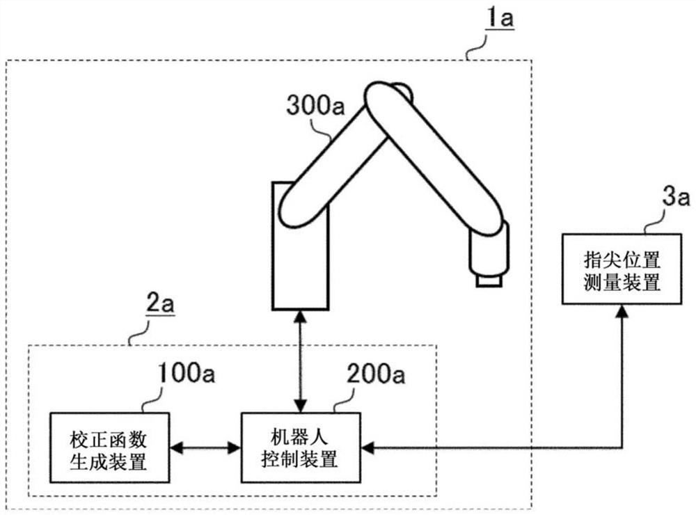
[0041] figure 1 It is a figure which shows an example of the structure of the robot system 1a and the robot control system 2a which have the correction function generation apparatus 100a concerning Embodiment 1 of this invention. The robot system 1a has: a robot having a robot arm 300a; and a robot control system 2a. In addition, the robot control system 2a includes a correction function generation device 100a and a robot control device 200a. In addition, in figure 1 The illustration of parts of the robot other than the robot arm 300a is omitted in FIG.

[0042] A fingertip position measuring device 3a for measuring the three-dimensional position of the fingertip of the robot arm 300a is connected to the robot system 1a. As the fingertip position measuring device 3a, for example, a laser distance sensor, a visual sensor, or the like is used. Here, the fingertip of the robot arm 300a is the tip of the robot arm 300a, and refers to a part that acts on the work object. The f...

Embodiment approach 2

[0099] The correction function generating device of the present embodiment evaluates the displacement of the fingertip position from the reference position to generate a correction function. Figure 11 It is a figure which shows an example of the structure of the robot system 1b and the robot control system 2b which have the correction function generation apparatus 100b concerning Embodiment 2 of this invention. The robot system 1b has: a robot having a robot arm 300a; and a robot control system 2b. In addition, the robot control system 2b has a correction function generation device 100b and a robot control device 200b. A fingertip position measuring device 3b is connected to the robot system 1b. exist Figure 11 In the robot system 1b shown, other structures except the robot control system 2b and the fingertip position measuring device 3b are the same as figure 1 The robot system 1a in Embodiment 1 shown is the same. Next, points of difference from the correction function...

Embodiment approach 3

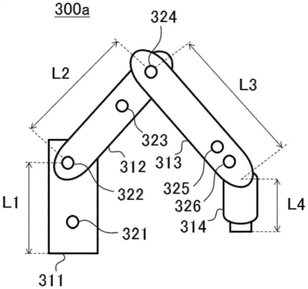
[0116] The correction function generation device 100a according to the first embodiment and the correction function generation device 100b according to the second embodiment are configured to generate a correction function based on temperature information measured by the temperature sensors 321 to 326 mounted on the robot arm 300a. On the other hand, the correction function generating device 100c of the present embodiment also generates a correction function using the ambient temperature around the robot arm 300a.

[0117] Figure 16 It is a figure which shows an example of the structure of the robot system 1c and the robot control system 2c which have the correction function generation apparatus 100c concerning Embodiment 3 of this invention. The robot system 1c has: a robot having a robot arm 300a; and a robot control system 2c. In addition, the robot control system 2c includes a correction function generating device 100c and a robot control device 200c. A fingertip positi...


PUM


Abstract

The present invention makes it possible to control the position of the tip of a robot arm with high precision without increasing the points for which the position is measured. A correction function-generating device (100a) for generating a correction function to be used for controlling the position of the tip of a jointed robot arm is provided with: an information-acquiring unit (110a) for acquiring temperature information measured at a specified position of the robot arm and a measured position obtained by measuring the angle of a joint at the time point at which the temperature information was measured and the position of the tip at the time point at which the temperature information was measured; a tip position-estimating unit (120a) for determining an estimated position by estimating the position of the tip at the time point at which the temperature information was acquired on the basis of the acquired joint angle; and a correction function-determining unit (130a) for determining acorrection function, which is a function that has temperature information as a variable, on the basis of the results of comparing the measured position with the estimated position.

Description

technical field [0001] The present invention relates to a correction function generating device for generating a correction function used to control the position of a fingertip of a robot arm having a joint, a robot control system and a robot system including the correction function generating device. Background technique [0002] In factories and the like, robot arms are used to perform repetitive tasks with high precision. However, due to the heat generated by the motor for driving the robot arm and the influence of ambient temperature changes, a phenomenon in which the temperature of the robot arm changes occurs. As the temperature of the robot arm changes, whereby the robot arm thermally expands or contracts, the position of the fingertip of the robot arm changes. As a result, there arises a problem that the robot control system cannot control the position of the fingertip of the robot arm with high precision. That is, there is a problem that the positioning accuracy o...

Claims


Application Information

Patent Timeline
IPC IPC(8): B25J9/10G05B19/404
CPCG05B19/404
Inventor 儿岛谅
Owner MITSUBISHI ELECTRIC CORP
Why Eureka
Try Eureka