Supercharge Your Innovation With Domain-Expert AI Agents!

Vehicle compartment temperature control device

An indoor temperature and control device technology, which is applied in special positions of vehicles, seat heating/ventilation devices, vehicle seats, etc., can solve problems such as increased production costs, increased power consumption, and inability to ensure power saving.

Pending Publication Date: 2020-10-23
MAZDA MOTOR CORP
View PDF9 Cites 0 Cited by
  • Summary
  • Abstract
  • Description
  • Claims
  • Application Information

AI Technical Summary

Problems solved by technology

[0013] However, when a large number of temperature control devices such as heating panels are installed on the inner wall of the vehicle, there is a concern that the production cost will increase due to the increase in the number of parts of the vehicle.
In addition, the power consumption for operating a large number of heating plates increases, and the expected power saving may not be ensured.

Method used


Image

  • Vehicle compartment temperature control device
  • Vehicle compartment temperature control device
  • Vehicle compartment temperature control device

Examples


Embodiment Construction

[0039] Hereinafter, embodiments of the present invention will be described in detail with reference to the drawings.

[0040] The following description is merely an illustration of the application of the present invention to an indoor temperature control device for a vehicle, and does not limit the present invention, its application objects, or its uses.

[0041] In addition, in the drawings, the arrow F direction is described as the forward direction of the vehicle, the arrow L direction is referred to as the left direction, and the arrow U direction is described as the upward direction.

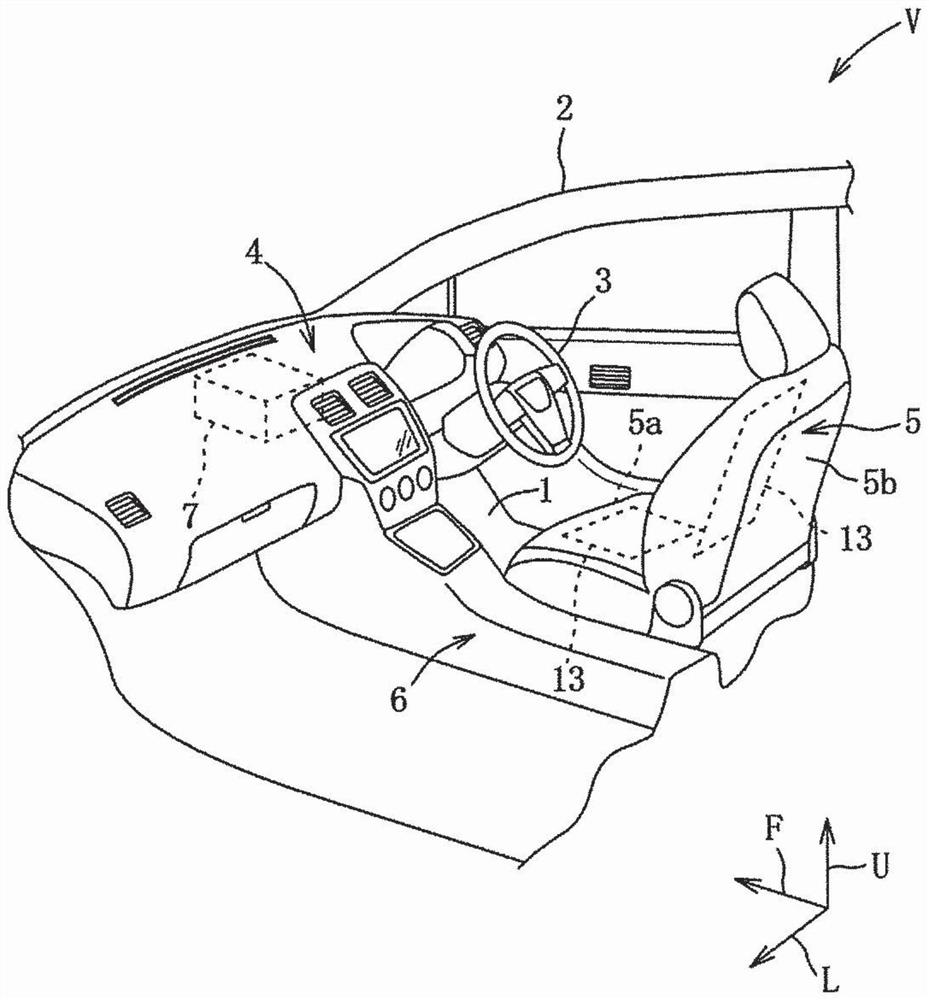
[0042] Below, according to Figures 1 to 20 Embodiments of the present invention will be described. exist figure 1 In , in order to show the main part of the cabin structure, the part around the driver's seat in the front right half of the cabin is enlarged and shown.

[0043] Such as figure 1 , 2 As shown, the vehicle V involved in this embodiment includes the following: a base plate ...


PUM


Abstract

Provided is a vehicle compartment temperature control device that can save power whilst also ensuring the thermal comfort of a passenger. This vehicle compartment temperature control device 10 can control the thermal comfort of a passenger in a seated posture in a seat. The device comprises: first interior members having a temperature control mechanism layer 13 in a front part 1a, an intermediarypart 1b, a front centre part 2c, a front lower part 2g, a front-surface lower part 4f, a seat cushion 5a and a right surface front upper part 6b, said parts constituting a first area in which the temperature of the legs of the passenger can be regulated; second interior members having a temperature control mechanism layer 13 different from the temperature control mechanism layers 13 in the first area in a steering wheel 3, a front-surface centre part 4e and a seat back 5b which constitute a second area which is positioned above a first interior members and in which the temperature of the above-leg region of the passenger can be regulated; and an ECU 30. The ECU 30 performs control so that the temperature of the temperature control mechanism layers 13 in the first area is higher than the temperature of the temperature control mechanism layers 13 in the second area.

Description

technical field [0001] The present invention relates to an indoor temperature control device for a vehicle, and more particularly to an indoor temperature control device for a vehicle capable of controlling the thermal comfort of an occupant in a sitting posture. Background technique [0002] From the viewpoint of warming the head and warming the feet, vehicle air conditioners have conventionally provided underfoot outlets capable of supplying warm air to the occupant's feet to increase the ambient temperature around the occupant's lower limbs. [0003] In the environment of the vehicle interior, the occupied space of the occupant is narrow, the posture is restricted, and the thermal insulation between the occupant and the external environment is low. Therefore, a large amount of energy consumption is required to ensure the thermal comfort of the occupant. [0004] Here, the thermal comfort is defined by ASHRAE (American Society of Heating, Refrigerating, and Air-Conditionin...

Claims


Application Information

Patent Timeline
Patent Type & Authority Applications(China)
IPC IPC(8): B60H1/22B60H1/00B60N2/56
CPCB60H1/22B60H1/00B60R13/02B60H1/00285B60H1/00292B60H1/00295B60H2001/00307B60H1/00478B60H1/2227B60N2/5685B60N2/5692B60H1/00035B60H1/00835
Inventor 横田和也落合洸矢大住敏彦金石纯司吉末知弘加岛利浩
Owner MAZDA MOTOR CORP
Features
  • R&D
  • Intellectual Property
  • Life Sciences
  • Materials
  • Tech Scout
  • Unparalleled Data Quality
  • Higher Quality Content
  • 60% Fewer Hallucinations
Learn More