Gyratory flywheel with rapid acceleration structure

An acceleration structure and flywheel technology, applied in the field of boomerangs, can solve problems such as inconvenient use, single function, and difficulty in achieving the effect of boomerang recovery

Pending Publication Date: 2020-10-27
广东星宝玩具有限公司
View PDF0 Cites 0 Cited by
  • Summary
  • Abstract
  • Description
  • Claims
  • Application Information

AI Technical Summary

Problems solved by technology

[0003] However, the traditional boomerangs currently on the market are relatively simple in functionality and very inconvenient to use. Most of the traditional boomerangs are thrown out by people, and the strength cannot be accurately grasped, so it is difficult to achieve the effect of boomerang recovery.

Method used


Image

  • Gyratory flywheel with rapid acceleration structure
  • Gyratory flywheel with rapid acceleration structure
  • Gyratory flywheel with rapid acceleration structure

Examples


Embodiment 1

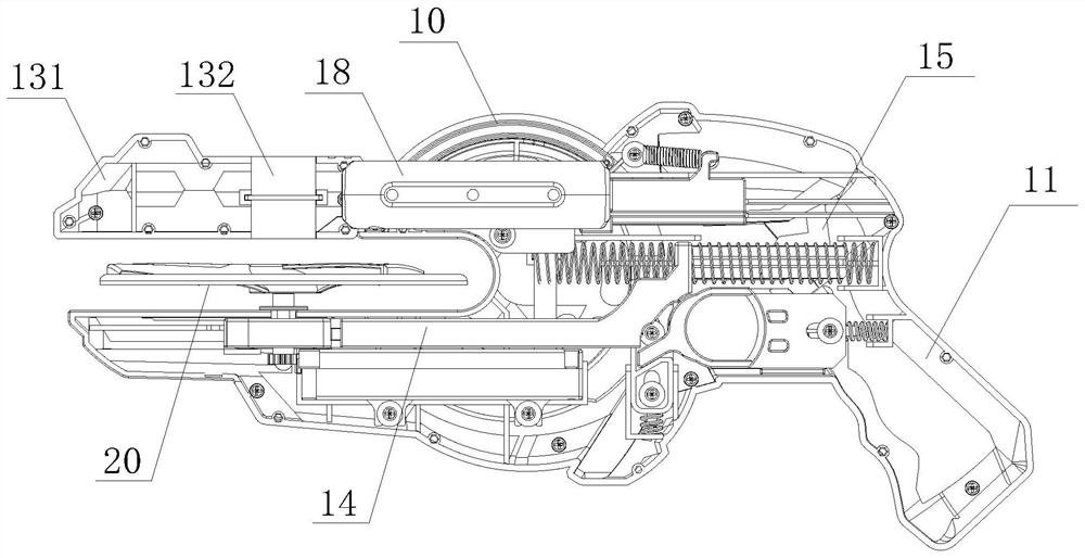
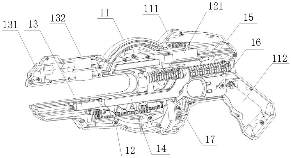
[0034] see Figure 1-7 , the present invention provides a technical solution: a spinning flywheel with a fast acceleration structure, including: a firing gun 10 and a spinning flywheel 20 .

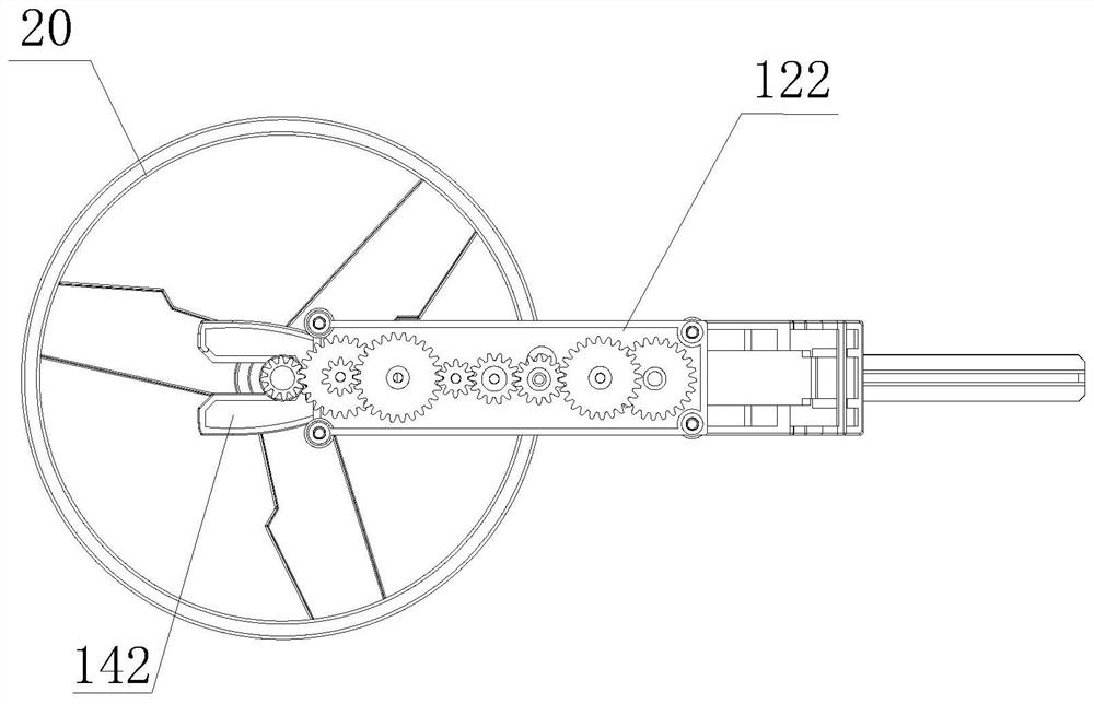
[0035] Wherein, the launch gun 10 includes a launch gun casing 11, an acceleration assembly 12 and a launch mechanism 14, the acceleration assembly 12 includes a pull tooth 121, a gear box 122 and a conversion main shaft 124, and the inside of the gear box 122 is installed by rotating a rotating shaft. In the transmission gear assembly 123 , the upper and lower ends of the conversion main shaft 124 are fixedly equipped with main shaft gears 125 , and the conversion main shaft 124 is meshed with the pull teeth 121 .

[0036] Further, the pulling stroke of the pulling tooth 121 is about 45mm.

[0037] Further, pulling the pulling tooth 121 drives the conversion main shaft 124 to rotate, and accelerates the main shaft gear 125 to rotate. The main shaft gear 125 realizes a super large speed ...

Embodiment 2

[0057] see Figure 1-7 , the present invention provides a technical solution: a spinning flywheel with a fast acceleration structure, including: a firing gun 10 and a spinning flywheel 20 .

[0058] Wherein, the revolving flywheel 20 includes a flywheel hub 21 and flywheel blades 22, and the flywheel blades 22 are provided with several pieces, wherein several pieces of the flywheel blades 22 are fixedly installed on the inner wall surface of the flywheel hub 21, wherein several pieces of the flywheel blades 22 is fixedly connected with an acceleration shaft 24, and a hexagonal piece 23 is fixedly installed on the outside of the acceleration shaft 24 near the top end, and a flywheel body gear 26 is fixedly installed on the outside of the acceleration shaft 24 near the bottom end.

[0059] Further, pulling the pulling tooth 121 drives the conversion main shaft 124 to rotate, and accelerates the main shaft gear 125 to rotate. The main shaft gear 125 realizes a super large speed c...


PUM


Abstract

The invention discloses a gyratory flywheel with a rapid acceleration structure, wherein the gyratory flywheel comprises a launching gun and a gyratory flywheel body, wherein the launching gun comprises a launching gun shell, an acceleration assembly and a launching mechanism, and the acceleration assembly and the launching mechanism are both fixedly arranged in the launching gun shell; the launching gun is combined with the gyratory flywheel body; the gyratory flywheel body is launched in the form of a gun; the flywheel body utilizes aerodynamic principle and automatically swivels back, the bottom of the gyratory flywheel body is newly added with a main shaft, the gyratory flywheel body can rotate and play like a rotating body on a plane; through a gear bouncing structure, the infinite acceleration function of the gun is achieved, and the far and high convolution characteristics of the flywheel are achieved, the functional diversity of the product is guaranteed, two persons can launchat the same time for competition and can also play independently, and the safety and the playability of the product are fully guaranteed in the aspects of structure, materials and appearance.

Description

technical field [0001] The invention relates to the technical field of boomerangs, in particular to a boomerang flywheel with a fast acceleration structure. Background technique [0002] The boomerang is also known as boomerang, self-returner, boomerang and other names. As the name implies, it will fly back after flying out. Its shapes include "V", banana, bell, and three leaves. Shape, "ten" shape, multi-leaf shape, and other shapes. The cutting surface of the wing of the boomerang makes the direction of the air lift on the boomerang be the upward direction (aerodynamics), making the body of the boomerang stable. , the boomerang is the same as the rotating body, its shaft rotates around a straight line (rigid body dynamics), lift and stability make the boomerang rise, and the rotation of the shaft makes the boomerang fly back. [0003] However, the traditional boomerangs currently on the market have relatively simple functions and are very inconvenient to use. Most of the ...

Claims


Application Information

Patent Timeline
Patent Type & Authority Applications(China)
IPC IPC(8): A63H33/18
CPCA63H33/18
Inventor 陈铃铃
Owner 广东星宝玩具有限公司
Why Eureka
Try Eureka