

Cantilever crane special for metallurgy
A cantilever crane and metallurgical technology, which is applied in the direction of cranes, transportation and packaging, etc., can solve the problem that the length of the cantilever cannot be adjusted, and achieve the effect of enriching the use function, enhancing the lifting capacity and increasing the lifting range
- Summary
- Abstract
- Description
- Claims
- Application Information
AI Technical Summary
Problems solved by technology
Method used
Image

Examples
Embodiment Construction
[0020] The following will clearly and completely describe the technical solutions in the embodiments of the present invention with reference to the accompanying drawings in the embodiments of the present invention. Obviously, the described embodiments are only some of the embodiments of the present invention, not all of them. Based on the embodiments of the present invention, all other embodiments obtained by persons of ordinary skill in the art without making creative efforts belong to the protection scope of the present invention.
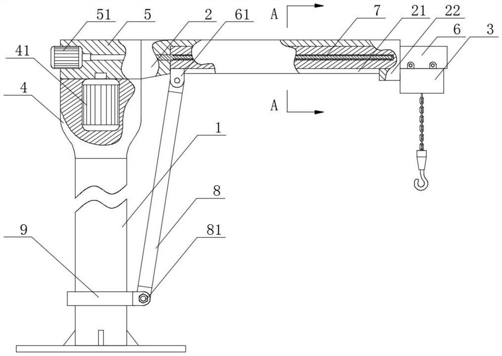
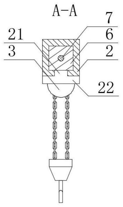
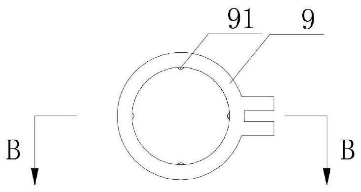
[0021] see Figure 1-5 , the present invention provides a technical solution, a special cantilever crane for metallurgy, including a column 1, a cantilever 2 and an electric hoist 3, the top of the column 1 is fixedly connected with a rotary drive part 4, and the inner cavity of the rotary drive part 4 is provided with a rotary motor 41. The power output end of the slewing motor 41 penetrates the upper surface of the slewing drive part 4 and is s...
PUM
 Abstract
Description
Claims
Application Information