An Automatic Tape Laying Trajectory Planning Method Based on Isogeodesic Curvature Curves

A geodesic curvature and trajectory planning technology, applied in instrumentation, design optimization/simulation, image data processing, etc., can solve problems such as large local deformation of prepreg tape, and achieve the effect of reducing the amount of deformation and reducing the degree of cumbersomeness

Active Publication Date: 2022-05-24
CHANGSHA UNIVERSITY OF SCIENCE AND TECHNOLOGY
View PDF11 Cites 0 Cited by
  • Summary
  • Abstract
  • Description
  • Claims
  • Application Information

AI Technical Summary

Problems solved by technology

However, offsets between each small geodesic segment may cause large local deformations in the prepreg tape

Method used


Image

  • An Automatic Tape Laying Trajectory Planning Method Based on Isogeodesic Curvature Curves
  • An Automatic Tape Laying Trajectory Planning Method Based on Isogeodesic Curvature Curves
  • An Automatic Tape Laying Trajectory Planning Method Based on Isogeodesic Curvature Curves

Examples


Embodiment 1

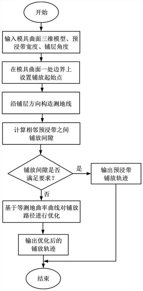
[0046] like figure 1 As shown in the figure, an automatic tape laying trajectory planning method based on an equal geodesic curvature curve is characterized in that, it includes the following steps:

[0047] S1. Input the three-dimensional model of the mold surface to be laid, the width W of the prepreg tape, and the laying direction of the prepreg tape;

[0048] S2. Select a boundary of the mold surface, and set a plurality of starting points for laying prepreg tapes on the boundary, so that the distance between the adjacent laying starting points on the boundary of the mold surface is W+s, where the unit of s is is mm and s∈(0,1];

[0049] S3. Construct a geodesic line along the starting point set in step S2 respectively, until the trajectory of the geodesic line reaches another boundary of the curved surface, and the direction of the geodesic line is the same as the laying direction of the prepreg tape in step S1;

[0050] S4. Using the geodesic constructed in step S3 as ...

Embodiment 2

[0081] A kind of automatic tape laying trajectory planning method based on equal geodesic curvature curve, is characterized in that, comprises the following steps:

[0082] S1. Input the three-dimensional model of the mold surface to be laid, the width W of the prepreg tape, and the laying direction of the prepreg tape;

[0083] S2. Select a boundary of the mold surface, and set a plurality of starting points for laying prepreg tapes on the boundary, so that the distance between the adjacent laying starting points on the boundary of the mold surface is W+s, where the unit of s is is mm and s∈(0,1];

[0084] S3. Construct a geodesic line along the starting point set in step S2 respectively, until the trajectory of the geodesic line reaches another boundary of the curved surface, and the direction of the geodesic line is the same as the laying direction of the prepreg tape in step S1;

[0085] S4. Using the geodesic constructed in step S3 as the proposed laying track of the pre...

Embodiment 3

[0125] In this embodiment, a process for automatic tape laying trajectory planning on a hyperboloid mold is provided, as follows:

[0126] S1. Input the 3D model of the hyperboloid mold, the width of the prepreg tape is 150mm, and the layering direction is 0 degrees; such as Figure 4 As shown, the size of the hyperboloid mold is 1000mm×5000mmm;

[0127] S2. Set up multiple prepreg tape laying starting points on one boundary of the hyperboloid mold, and at the same time ensure that the distance between the adjacent laying starting points on the mold boundary is 151mm;

[0128] S3. Such as Figure 5 As shown, starting from each layup start point, construct geodesics along the layup direction until the locus of the geodesics reaches the other boundary of the surface;

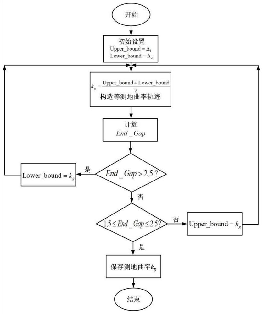
[0129] S4. Take the geodesic line as the proposed tape laying track during the laying process of the prepreg tape, and calculate the size of the laying gap between the adjacent prepreg tapes. Large laying gap, ...


PUM


Abstract

The invention discloses an automatic tape-laying trajectory planning method based on isogeodetic curvature curves, which includes inputting the three-dimensional model of the curved surface of the mold to be laid, the width W of the prepreg tape, and the laying direction of the prepreg tape, and the setting distance is W The starting point of +s, and construct the geodesic line according to the starting point, use the geodesic line as the planned laying track of the prepreg tape, and calculate the laying gap between all adjacent prepreg tapes; The tape laying trajectory is corrected to obtain the final tape laying trajectory. The present invention can plan the tape laying track on the non-developable curved surface, which reduces the cumbersomeness of the tape laying track planning process. Through the above track planning, it can effectively ensure that there will be no coverage between adjacent prepreg tapes after laying, and the corresponding Adjacent prepreg tapes meet clearance requirements.

Description

technical field [0001] The invention relates to the technical field of automatic tape laying and forming of composite materials, and in particular relates to an automatic tape laying trajectory planning method based on an equal geodesic curvature curve. [0002] technical background [0003] Automatic tape laying technology is a typical representative of composite material forming automation, and an important way to achieve "low-cost, high-performance, high-efficiency" manufacturing of composite materials. It is widely used in the manufacture of aerospace high-performance composite material structures. Trajectory planning is a key link in automatic tape laying technology, which directly affects the accuracy and efficiency of the laying process and the quality of the final product. The trajectory planning of automatic tape laying has the following requirements: 1. Ensure that the wrinkles or stretches generated by a single strip of material are as small as possible; 2. Ensure ...

Claims


Application Information

Patent Timeline
Patent Type & Authority Patents(China)
IPC IPC(8): G06F30/20G06T19/20
CPCG06F30/20G06T19/20
Inventor 张鹏黄龙尹来容
Owner CHANGSHA UNIVERSITY OF SCIENCE AND TECHNOLOGY
Why Eureka
Try Eureka