
Board card connection architecture and communication equipment with same

A board and connector technology, applied in the direction of selection devices, electrical components, etc., can solve the problems that the orthogonal architecture does not have the cluster function and the heat generated by the equipment is large

Active Publication Date: 2020-10-27
ZTE CORP
View PDF5 Cites 0 Cited by
  • Summary
  • Abstract
  • Description
  • Claims
  • Application Information

AI Technical Summary

Problems solved by technology

[0004] The first purpose of this application is to provide a board connection architecture to solve the problem that the existing orthogonal architecture does not have a cluster function and the heat generated by the equipment is large question

Method used


Image

  • Board card connection architecture and communication equipment with same
  • Board card connection architecture and communication equipment with same
  • Board card connection architecture and communication equipment with same

Examples


Embodiment 1

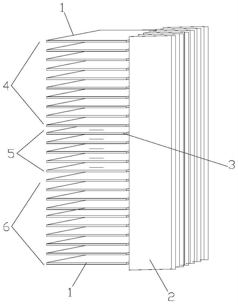
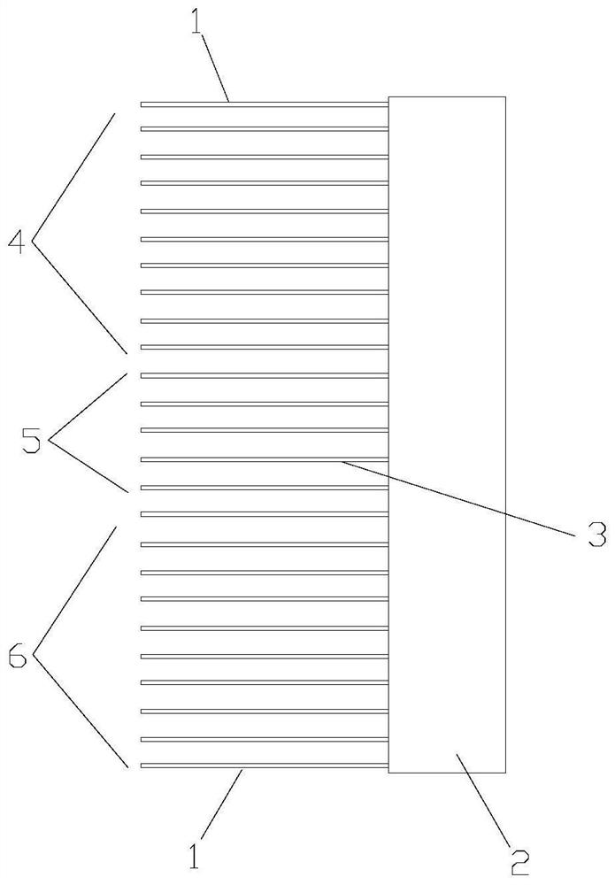
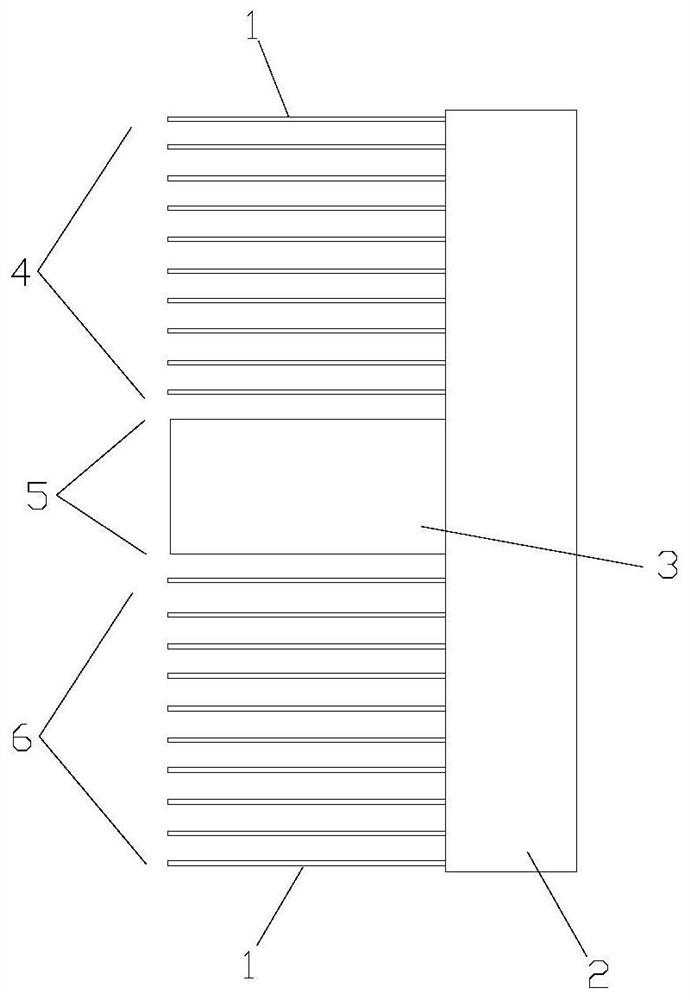
[0019] combined with Figure 1-3 As shown, this embodiment provides a board-card connection architecture, including a line card 1, a switch board 2, and a cluster optical interface board 3. The line card 1, the switch board 2, and the cluster optical interface board 3 are essentially boards with different functions. Card, the line card 1 is used for a device interface between the access line of the switch, router or other network equipment and the access device, the switch board 2 is provided with a switch chip 10, which plays the role of connecting each device, and the cluster optical interface board 3 is provided with an optical interface, which can be connected with other devices such as the switching board 2 to realize the cluster function.

[0020] In order to facilitate installation, a plurality of exchange plates 2 in this embodiment are arranged in parallel at intervals to form a group of exchange plates 2, and one side (left side in the figure) of the exchange plate 2...

Embodiment 2

[0028] This embodiment provides a communication device, which includes the board connection structure in Embodiment 1, and further includes a device frame 13, a power supply 14, a cooling fan 15, a main control board 16 and other structures. combined with Figure 5 with 6 As shown, since two board connection architectures are provided in Embodiment 1 ( figure 2 with 3 shown), so the communication device of this embodiment also has two structural forms, one is as Figure 5 The cluster optical interface board shown is vertically connected to the switch board, and the other is as shown in Image 6 The shown cluster optical interface board is coplanarly connected to the switching board.

[0029] Specifically, the board connection structure, power supply 14, cooling fan 15 and main control board 16 of this embodiment are all installed on the main control board 16, the power supply 14 supplies power for the electrical components of the equipment, and the main control board 16 a...


PUM


Abstract

The invention discloses a board card connection architecture and communication equipment with the architecture. The board card connection architecture comprises an exchange board and a line card connected with the exchange board; the exchange board is provided with a line card installation area and a cluster optical interface board installation area; the line card is installed in the line card installation area; the cluster optical interface board installation area is used for installing a cluster optical interface board; and the cluster optical interface board is connected with the exchange board. According to the board card connection architecture provided by the invention, the cluster optical interface board is installed in the cluster optical interface board installation area, and thecluster optical interface board is in cross connection with the exchange board, so that the cluster function can be realized, the overlapping of the heating area of the line card and the heating areaof the exchange board is reduced, the heat dissipation capability of equipment is effectively enhanced, and the service life of the equipment is prolonged.

Description

technical field [0001] The present application relates to the technical field of electronic circuits, in particular to a board connection architecture and a communication device with the architecture. Background technique [0002] At present, the electronic systems of communication equipment such as servers, routers, and switches are usually composed of a number of interconnected and interacting basic circuits with specific functions. Most of the functional circuits are deployed and integrated on circuit boards. Connect the switch board through the connector to realize the electrical connection between the functional circuits. Boards of existing communication devices tend to be arranged in an orthogonal architecture (OD) layout, where multiple line cards arranged in parallel and multiple switch boards are vertically connected to each other, so as to realize the electrical connection of various functional circuit parts of the communication device. [0003] However, in order ...

Claims


Application Information

Patent Timeline
IPC IPC(8): H04Q1/02
CPCH04Q1/035H04Q1/155
Inventor 张远望
Owner ZTE CORP
Learn More