Mode switching method, terminal and network equipment

A technology of mode switching and network equipment, applied in the field of communication, which can solve problems such as poor terminal transmission flexibility

Active Publication Date: 2020-10-27
VIVO MOBILE COMM CO LTD
View PDF8 Cites 1 Cited by
  • Summary
  • Abstract
  • Description
  • Claims
  • Application Information

AI Technical Summary

Problems solved by technology

[0003] Embodiments of the present invention provide a mode switching method, terminal and...

Method used


Image

  • Mode switching method, terminal and network equipment
  • Mode switching method, terminal and network equipment
  • Mode switching method, terminal and network equipment

Examples


Embodiment approach

[0061] As an optional implementation, the method also includes:

[0062] When the first timer expires, entering the second mode, wherein the entering the second mode includes:

[0063] switch from the first mode to the second mode, or maintain the second mode.

[0064] Wherein, the terminal may be in the second mode, and the first timer times out, so as to maintain the second mode, or it may be that the terminal is in the first mode, and the first timer times out, so that the first mode switches to the second mode Two modes. For example: when the second timer expires and the first timer does not expire, if the PDCCH is received, restart the second timer and switch back from the second mode to the first mode. In this case, the terminal may be When the terminal is in the first mode, the first timer times out.

[0065] In this implementation manner, since the second mode is entered when the first timer times out, the energy consumption of the terminal can be saved.

[0066] O...


PUM


Abstract

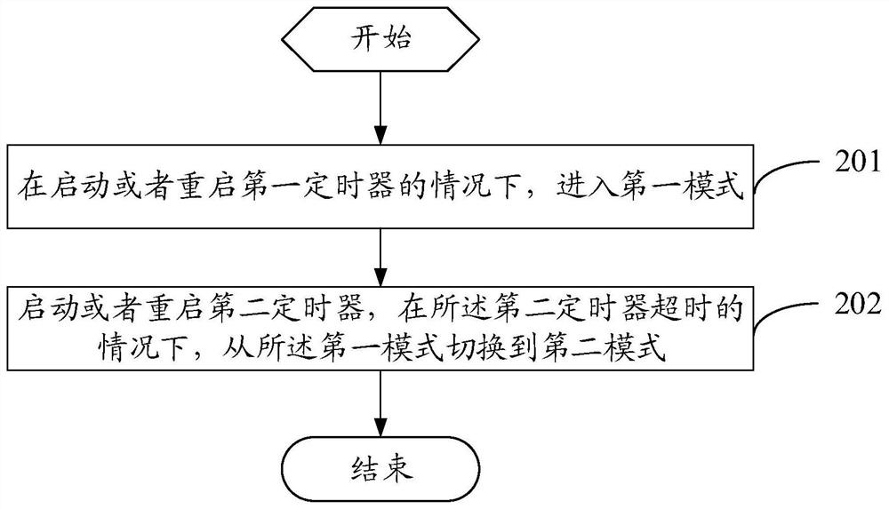
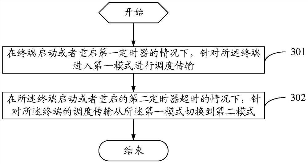
The embodiment of the invention provides a mode switching method, a terminal and network equipment, and the method comprises the steps: entering a first mode under the condition that a first timer isstarted or restarted, and enabling the first timer to be drx-Inactivity Timer; and starting or restarting a second timer, and switching from the first mode to a second mode under the condition that the second timer is overtime. According to the embodiment of the invention, the transmission flexibility of the terminal can be improved, and the energy-saving effect of the terminal can also be improved.

Description

technical field [0001] The present invention relates to the field of communication technology, in particular to a mode switching method, terminal and network equipment. Background technique [0002] In the process of connected discontinuous reception (Connected Discontinuous Reception, CDRX), the terminal receives a physical downlink control channel (Physical Downlink Control Channel, PDCCH) indicating a new transmission (or called the initial transmission) during the active time (active time) , then the DRX inactivity timer (drx-InactivityTimer) can be started, and the terminal remains in the same mode after starting the drx-InactivityTimer. The downlink or uplink multiple-input multiple-output layer (DL / UL MIMO layer) mode leads to relatively poor flexibility of terminal transmission. Contents of the invention [0003] Embodiments of the present invention provide a mode switching method, a terminal and a network device, so as to solve the problem of relatively poor flex...

Claims


Application Information

Patent Timeline
IPC IPC(8): H04W76/28H04L5/00
CPCH04W76/28H04L5/0053Y02D30/70
Inventor 姜大洁潘学明沈晓冬
Owner VIVO MOBILE COMM CO LTD
Why Eureka
Try Eureka