Water conveying sleeve and molding machine

A molding machine and water transport technology, applied in the field of molding equipment, can solve problems such as difficulty in meeting process requirements

Pending Publication Date: 2020-10-30
MODERN PRECISION PLASTIC & MOLD SHENZHEN CO LTD +1
View PDF0 Cites 0 Cited by
  • Summary
  • Abstract
  • Description
  • Claims
  • Application Information

AI Technical Summary

Problems solved by technology

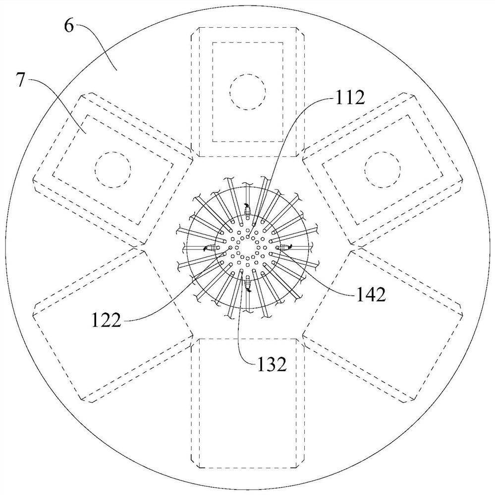
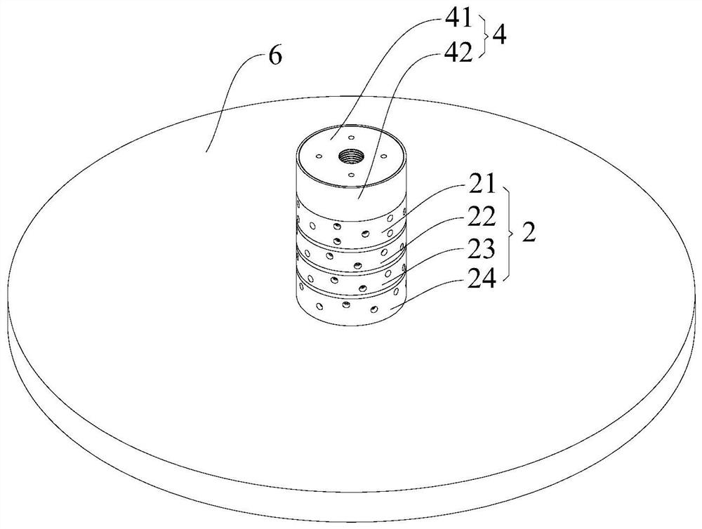
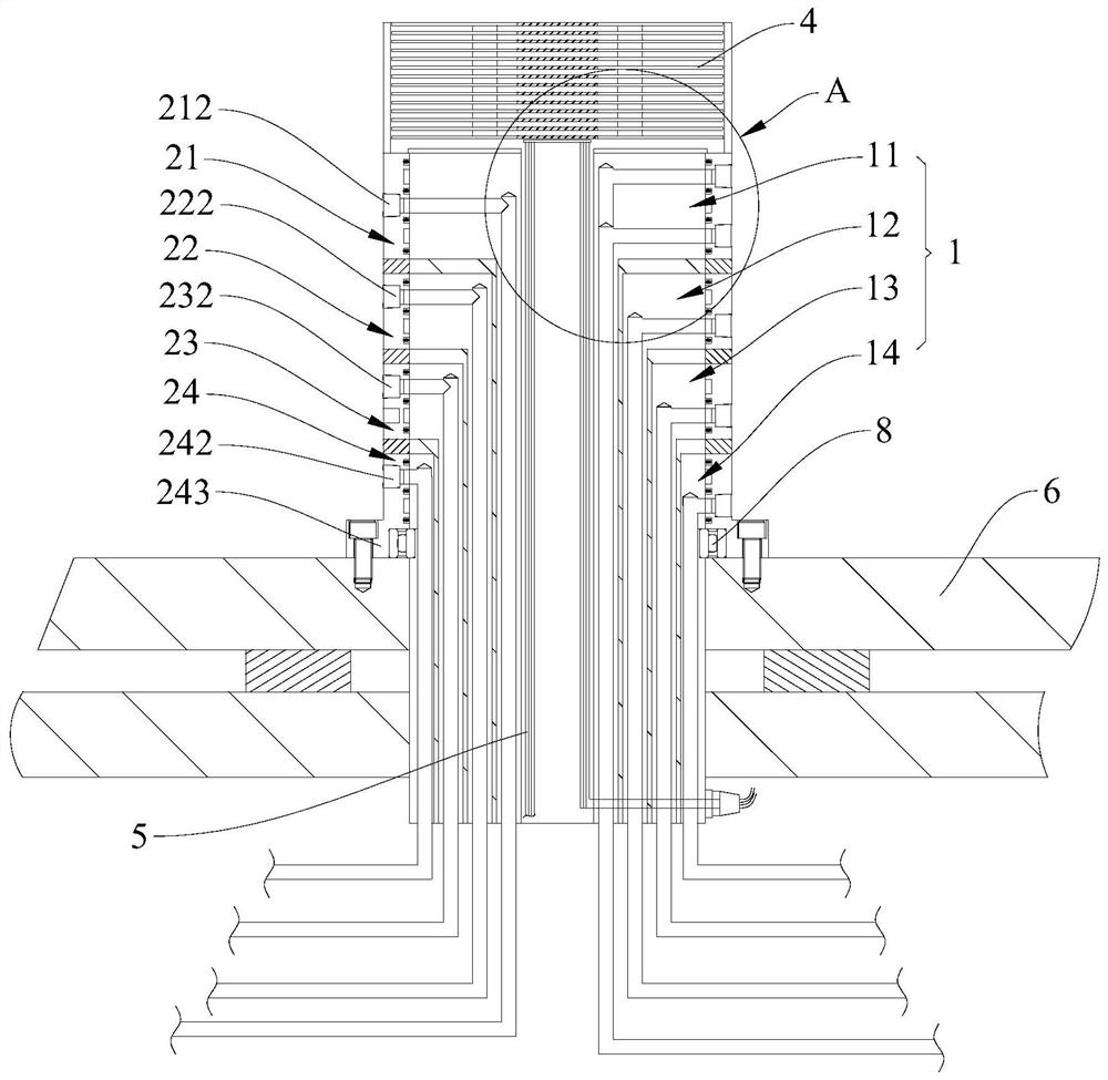
[0005] One of the purposes of the embodiments of the present application is to provide a water-carrying jacket, which aims to solve the technical pr

Method used


Image

  • Water conveying sleeve and molding machine
  • Water conveying sleeve and molding machine
  • Water conveying sleeve and molding machine

Examples


Embodiment Construction

[0033] Embodiments of the present application are described in detail below, examples of which are shown in the drawings, wherein the same or similar reference numerals denote the same or similar elements or elements having the same or similar functions throughout. The embodiments described below by referring to the figures are exemplary, and are intended to explain the present application, and should not be construed as limiting the present application.

[0034] In the description of the present application, it should be understood that the terms "length", "width", "upper", "lower", "front", "rear", "left", "right", "vertical", The orientation or positional relationship indicated by "horizontal", "top", "bottom", "inner", "outer", etc. are based on the orientation or positional relationship shown in the drawings, and are only for the convenience of describing the application and simplifying the description, rather than Nothing to indicate or imply that a referenced device or ...


PUM


Abstract

The application provides a water conveying sleeve and a molding machine. The water conveying sleeve comprises a stator and a rotor. The stator comprises a base. At least a first fixing sleeve is sleeved on the base. A first flow channel is formed in the base. A second flow channel is formed in the first fixing sleeve. The first flow channel and the second flow channel are respectively used for connecting with an external pipeline. The rotor is simultaneously sleeved on the base and the first fixing sleeve and is used for fixing on a rotary table. A first movable interface and a second movableinterface which are respectively used for connecting with a mould are formed in the rotor. An annular first conveying groove is formed in the rotor or the base. The first conveying groove is respectively communicated with the first movable interface and the first flow channel. An annular second conveying groove is formed in the rotor or the first fixing sleeve. The second conveying groove is respectively communicated with the second movable interface and the second flow channel. That the medium temperature of the first flow channel and the second flow channel will not affect each other can beensured, the use effect of the medium passing through the water conveying sleeve is improved, and the requirements of the corresponding technology are met.

Description

technical field [0001] The application belongs to the technical field of molding equipment, and more specifically, relates to a water-carrying jacket and a molding machine. Background technique [0002] Existing multi-station molding machines have multiple rotary stations, and the setting of multiple rotary stations can shorten as much as possible the time for the product to wait for cooling in the mold after molding, thereby improving the production efficiency of the product. At the same time, the multi-station molding machine can also realize the rapid switching between different processes in the production process of multi-material products and / or complex products, so as to realize continuous and rapid production. [0003] In actual production, different processes often have different requirements for molding conditions, so it is necessary to properly adjust the molding conditions in the mold. The more common is to adjust the temperature of the mold. For example, when the...

Claims


Application Information

Patent Timeline
IPC IPC(8): B29C45/73B29C45/06
CPCB29C45/06B29C45/73
Inventor 范开贤
Owner MODERN PRECISION PLASTIC & MOLD SHENZHEN CO LTD
Why Eureka
Try Eureka