
Box covering machine

A technology of cover boxes and racks, applied in the field of mechanical equipment, can solve problems such as labor-intensive and slow speed

Inactive Publication Date: 2020-10-30
周居先
View PDF8 Cites 0 Cited by
  • Summary
  • Abstract
  • Description
  • Claims
  • Application Information

AI Technical Summary

Problems solved by technology

[0002] The existing packaging boxes are generally packaged manually, such as shoe boxes, gift boxes and other simple packaging products. Since the sales of such packaged products are usually relatively large in the market, relying on manual packaging is slow and labor-intensive. , there is an urgent need for an automatic lid box equipment to improve production efficiency

Method used


Image

  • Box covering machine
  • Box covering machine
  • Box covering machine

Examples


Embodiment Construction

[0015] refer to Figure 1 to Figure 4 The embodiments of the present invention will be further described.

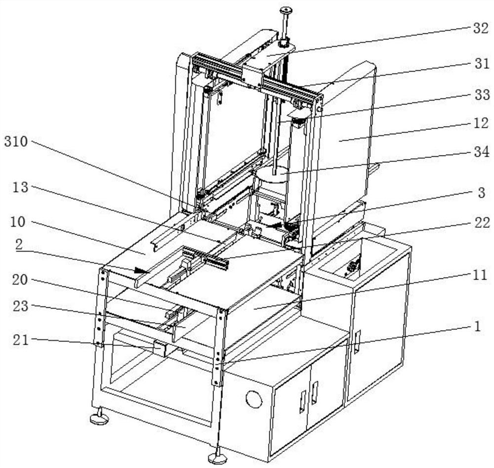
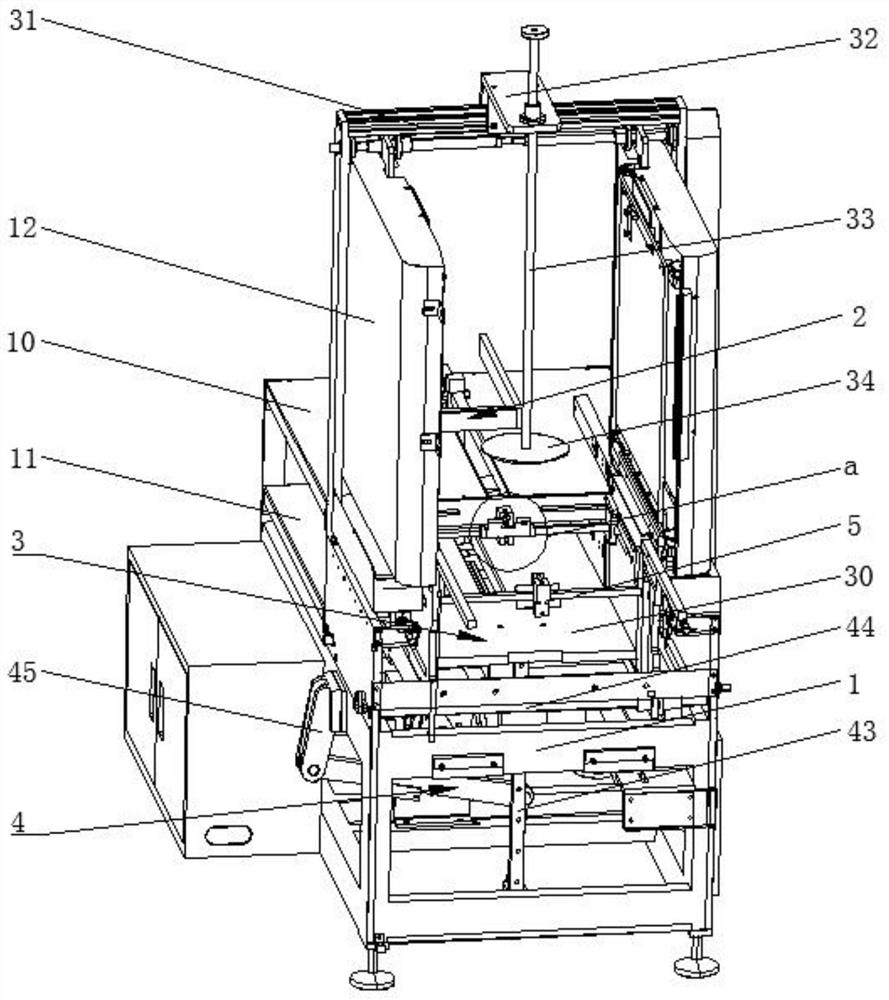
[0016] The invention discloses a box cover machine, which comprises a frame 1, and one end of the frame 1 is provided with a first feed plate 10 and a second feed plate 11 which are spaced up and down, and the first feed plate 10 and the second feeding plate 11 are provided with a synchronous pushing device 2, and the other end of the frame 1 is provided with a box cover device 3, and the box cover device 3 includes two respectively arranged on both sides of the frame 1. Fixed plate 12, described frame 1 is provided with the supporting plate 30 that is positioned between two fixed plates 12, and described frame 1 is provided with and is used for driving the driver 4 that slides up and down of dragging plate, in two fixed The top of the plate 12 is provided with a fixed frame 31, the central position of the fixed frame 31 is provided with a bracket 32, and the bracket 32...


PUM


Abstract

The invention discloses a box covering machine. The machine comprises a rack, wherein one end of the rack is provided with a first feeding plate and a second feeding plate which are arranged at an interval up and down, the first feeding plate and the second feeding plate are provided with synchronous pushing devices, and the other end of the rack is provided with a box covering device; the box covering device comprises two fixing plates separately arranged on two sides of the rack; the rack is provided with a material supporting plate located between the two fixing plates, the rack is providedwith a driving member for driving the material supporting plate to slide up and down, a fixing frame is arranged above the two fixing plates, a support is arranged at the center of the fixing frame,a pressing rod which is in sliding fit is arranged on the support, the pressing rod is located at the center of the material supporting plate, a circular pressing piece is arranged at the end, close to the material supporting plate, of the pressing rod, and sliding plates arranged in parallel are arranged at the positions, relative to the first feeding plate, of the two fixing plates. The box covering machine can automatically cover a box, and the production efficiency is improved.

Description

technical field [0001] The present invention relates to a mechanical device, and more particularly, it relates to a lid box machine. Background technique [0002] The existing packaging boxes are generally packaged manually, such as shoe boxes, gift boxes and other simple packaging products. Since the sales of such packaged products are usually relatively large in the market, relying on manual packaging is slow and labor-intensive. , there is an urgent need for an automatic lid box equipment to improve production efficiency. Contents of the invention [0003] Aiming at the deficiencies in the prior art, the purpose of the present invention is to provide a lid box machine capable of improving production efficiency. [0004] In order to achieve the above object, the present invention provides the following technical solutions: a box cover machine, including a frame, one end of the frame is provided with a first feed plate and a second feed plate arranged at intervals up and...

Claims


Application Information

Patent Timeline
IPC IPC(8): B65B7/28B65B43/54
CPCB65B7/2842B65B43/54
Inventor 周居先
Owner 周居先
Learn More