Supercharge Your Innovation With Domain-Expert AI Agents!

Cable pay-off trolley

A technology of pay-off block and cable, which is applied in the direction of conveying filamentous materials, thin material handling, transportation and packaging, etc. It can solve the problems of hidden safety hazards and complicated operation, and achieve the effect of reducing labor intensity

Pending Publication Date: 2020-10-30
HUNAN HUALITONG CABLE
View PDF0 Cites 0 Cited by
  • Summary
  • Abstract
  • Description
  • Claims
  • Application Information

AI Technical Summary

Problems solved by technology

The pay-off angle of the existing pay-off block is fixed, and the beam fixed structure is mostly used, that is, the whole pay-off block is arranged at the lower end of the beam, and the beam (such as the beam of the gantry crane) is used as the supporting and fixed body. , technicians are required to remove the entire pay-off block first, and then install it on the beam after replacing the wire wheel. The operation is complicated and there are potential safety hazards

Method used


Image

  • Cable pay-off trolley
  • Cable pay-off trolley
  • Cable pay-off trolley

Examples


Embodiment Construction

[0049] Embodiments of the present invention are described in detail below, examples of which are shown in the drawings, wherein the same or similar reference numerals designate the same or similar elements or elements having the same or similar functions throughout. The embodiments described below by referring to the figures are exemplary only for explaining the present invention and should not be construed as limiting the present invention.

[0050] In describing the present invention, it should be understood that the terms "center", "longitudinal", "transverse", "length", "width", "thickness", "upper", "lower", "front", " Rear", "Left", "Right", "Vertical", "Horizontal", "Top", "Bottom", "Inner", "Outer", "Axial", "Radial", "Circumferential" The orientation or positional relationship indicated by etc. is based on the orientation or positional relationship shown in the drawings, and is only for the convenience of describing the present invention and simplifying the descriptio...


PUM


Abstract

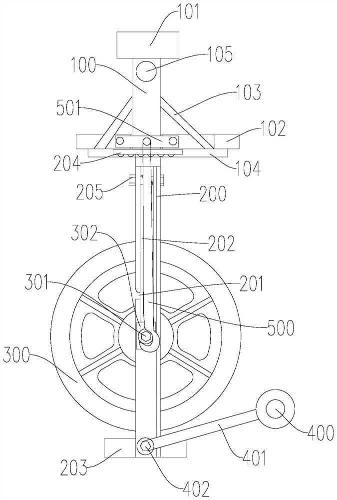
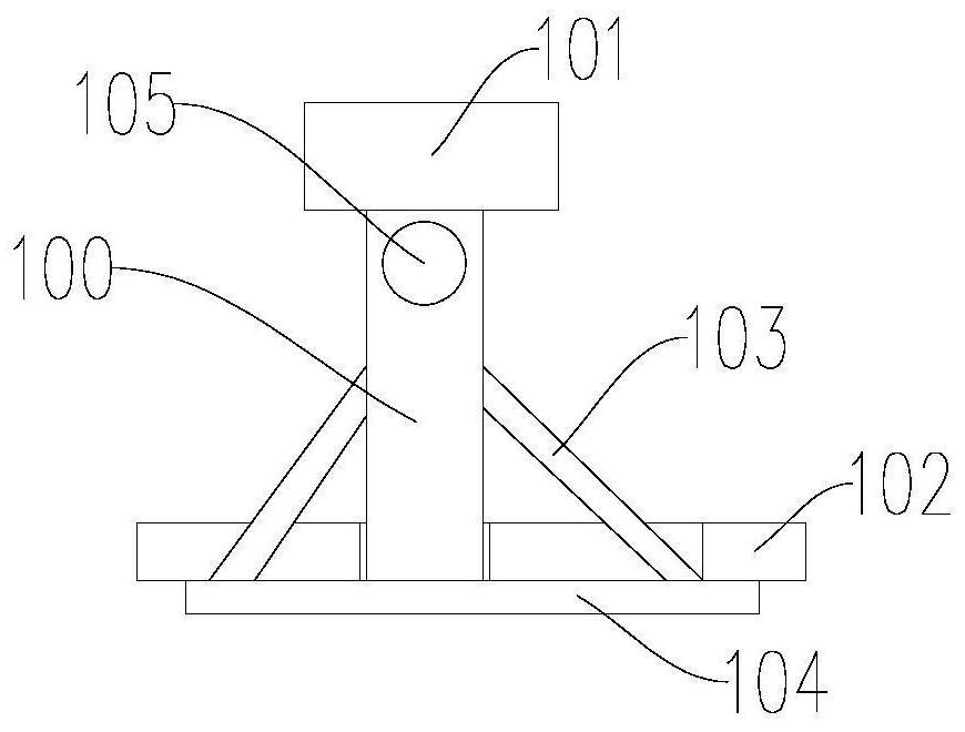
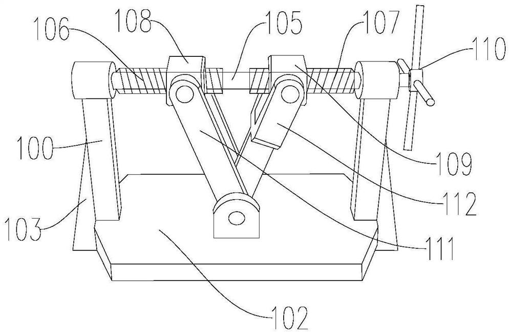
The invention discloses a cable pay-off trolley. The cable pay-off trolley is mainly used for suspending and paying off a cable during the twisting process of the cable. A first pay-off wheel with therewinding cable can be placed on or removed from a second mounting frame through a lifting device, specifically, the first pay-off wheel is pulled from a chute to an opening by using the lifting device, then, the second mounting frame is pushed so as to translate along the lower end of a first mounting frame, in the translation process, the first pay-off wheel is disengaged from the opening, thenthe first pay-off wheel with the rewinding cable is convenient for technicians to better replace, and the second mounting frame is sequentially loaded into for pay-off operation again according to the steps, so that the purpose of replacing the first pay-off pulley without disassembling and assembling the whole pay-off pulley is achieved, the operation is simple, and the safety is high; and meanwhile, a second pay-off wheel capable of rotating along with a second rotating shaft can adjust the pay-off angle and is more suitable for actual requirements in an actual production process.

Description

technical field [0001] The invention relates to a cable production equipment, in particular to a cable pay-off pulley. Background technique [0002] In the production process of the cable, especially the twisting process of the cable, it is necessary to use the pay-off block to carry out the hanging and unwinding of the cable. The pay-off angle of the existing pay-off block is fixed, and the beam fixed structure is mostly used, that is, the whole pay-off block is arranged at the lower end of the beam, and the beam (such as the beam of the gantry crane) is used as the supporting and fixed body. , need the technical staff to remove the whole pay-off tackle first, and install it on the crossbeam after replacing the wire wheel, the operation is complicated and there are potential safety hazards. Contents of the invention [0003] The present invention aims to solve at least one of the technical problems existing in the prior art. For this reason, the present invention propos...

Claims


Application Information

Patent Timeline
IPC IPC(8): B65H57/14B65H57/26B65H67/02
CPCB65H57/14B65H57/26B65H67/02B65H2701/341
Inventor 黄荣波
Owner HUNAN HUALITONG CABLE
Features
  • R&D
  • Intellectual Property
  • Life Sciences
  • Materials
  • Tech Scout
  • Unparalleled Data Quality
  • Higher Quality Content
  • 60% Fewer Hallucinations
Learn More