Dorsal bar flexural rigidity reinforcing device

A strengthening device and a technology of bending stiffness, which is applied in the joints of formwork/formwork/work frame, the preparation of building components on site, construction, etc. Long and other problems, to achieve a good reinforcement effect, eliminate deformation, and save time

Pending Publication Date: 2020-10-30
江苏佳搏实业发展集团有限公司
View PDF0 Cites 0 Cited by
  • Summary
  • Abstract
  • Description
  • Claims
  • Application Information

AI Technical Summary

Problems solved by technology

[0006] In terms of wall formwork reinforcement, the pull bolts can generally penetrate the wall, and occasionally there are cases where the pull bolts cannot be penetrated
For overrunning columns, the section size of a column is too large, resulting in too long tension bolts (made on site according to the size of the column), and once there is steel in the column, the tension bolts often cannot penetrate, which is the reason for the column formwork. Reinforcement poses certain difficulties

Method used


Image

  • Dorsal bar flexural rigidity reinforcing device
  • Dorsal bar flexural rigidity reinforcing device
  • Dorsal bar flexural rigidity reinforcing device

Examples


Embodiment 1

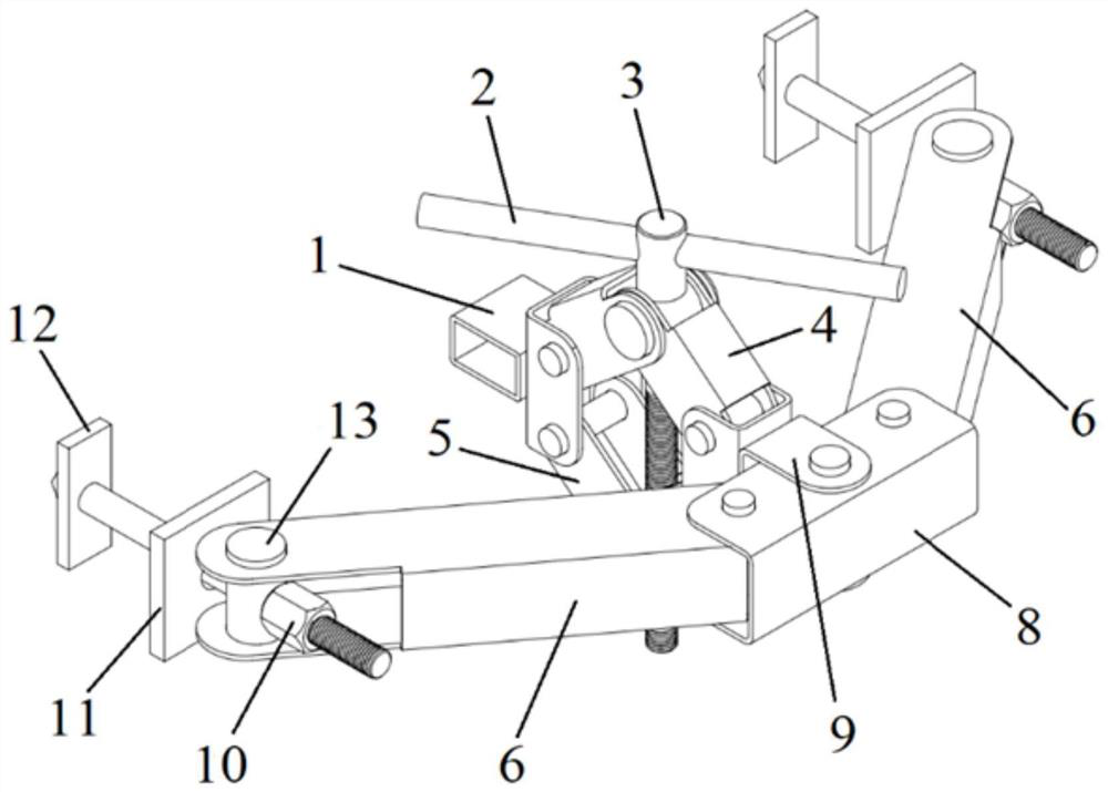
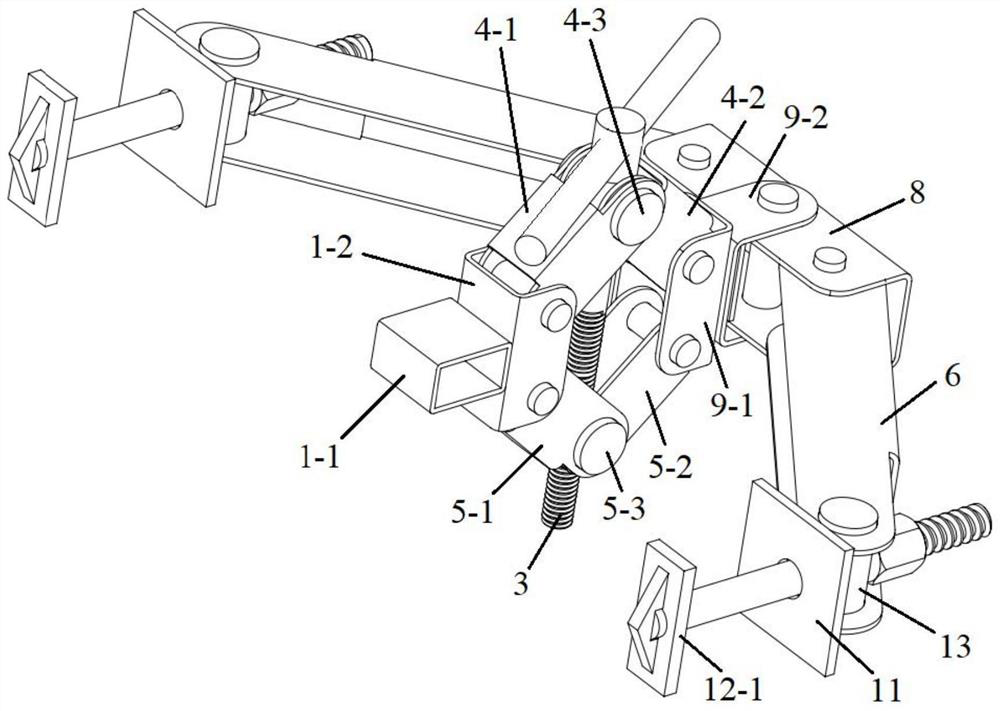
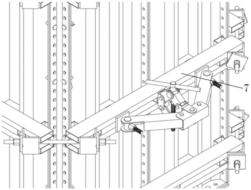
[0034] Such as Figure 1 to Figure 3 As shown, a back corrugated bending rigidity strengthening device includes a positioning block 1, a screw rod 3, a connecting rod 4, a connecting rod 2 5, a support rod 6, a U-shaped connecting rod 8, a nut 10, a T-shaped bolt 12, Hole pin 13;

[0035] Described connecting rod one 4 comprises hinged bar A4-1, bar B4-2 and the first column pin with hole 4-3, and the first end of bar A, bar B is hinged by the first column pin with hole, described A through hole is opened on the first pin with a hole, and the through hole is opened along the diameter direction of the first pin with a hole;

[0036] Described connecting rod two 5 comprises hinged bar C5-1, bar D5-2 and the second pin with hole 5-3, and the first end of bar C, bar D is hinged by the second pin with hole, described The second pin with holes is provided with an internally threaded hole matched with the screw mandrel 3, and the internally threaded hole is opened along the diamete...


PUM


Abstract

The invention discloses a dorsal bar flexural rigidity reinforcing device which comprises a positioning block, a screw rod, a first connecting rod, a second connecting rod, a support rod, a U shaped connecting rod, a nut, a T shaped bolt and a pored pin; the first connecting rod comprises a rod A and a rod B hinged to each other and a first pored pin; the second connecting rod comprises a rod C and a rod D hinged to each other and a second pored pin; the screw rod is sequentially arranged in a through hole and an internal threaded hole in a penetrating manner; the screw rod and the second pored pin are in threaded connection; the distance between the first pored pin and the second pored pin can be adjusted through rotating the screw rod; the two ends of the first connecting rod and the second connecting rod are hinged to a positioning block and a U shaped connecting rod; a support rod is hinged to the two ends of the U shaped connecting rod; the first end of the support rod is hinged to the U shaped connecting rod; the second end of the support rod is hinged to a T shaped bolt through the pored pin; the thread end of the T shaped bolt is mounted in the hole of the pored pin in a penetrating manner; and the nut locks a dorsal bar between the nut end of the T shaped bolt and the support rod.

Description

technical field [0001] The invention belongs to the technical field of reinforcement of building templates, and in particular relates to a device for strengthening the bending rigidity of back corrugated. Background technique [0002] The back flute is generally made of square tube or aluminum profile, called steel or aluminum back flute, and is often used to reinforce aluminum formwork or other forms of formwork. [0003] After the aluminum formwork of the wall and column is installed, it must be reinforced with pull bolts and back ribs to resist the lateral pressure on the aluminum formwork when pouring concrete. According to the requirements of the national standard, the formwork is arranged with several back flutes vertically, and each back flute is horizontally arranged with tension bolts at a certain interval. [0004] For wall formwork, Section 5.3.1 of the national standard "Technical Regulations for Composite Aluminum Alloy Formwork" (JGJ386-2016) stipulates that t...

Claims


Application Information

Patent Timeline
Patent Type & Authority Applications(China)
IPC IPC(8): E04G17/00
CPCE04G17/00
Inventor 古涛李修干魏敏
Owner 江苏佳搏实业发展集团有限公司
Why Eureka
Try Eureka