Tool deformation energy measuring device

A technology for measuring devices and deformation energy, applied in measuring devices, instruments, etc., can solve problems such as tool temperature rise and machining errors, and achieve the effect of offsetting bending deformation

Active Publication Date: 2021-05-14
NANJING UNIV OF AERONAUTICS & ASTRONAUTICS
View PDF10 Cites 1 Cited by
  • Summary
  • Abstract
  • Description
  • Claims
  • Application Information

AI Technical Summary

Problems solved by technology

In the processing system, the bending and torsional potential energy of the tool is usually converted into heat in the form of friction or vibration, which causes the temperature of the tool to rise, resulting in machining errors
In the existing related research fields, no scholars have considered this situation

Method used


Image

  • Tool deformation energy measuring device
  • Tool deformation energy measuring device
  • Tool deformation energy measuring device

Examples


Embodiment Construction

[0034] In order to clearly illustrate the technical characteristics of this patent, the following describes this patent in detail through specific implementation methods and in conjunction with the accompanying drawings.

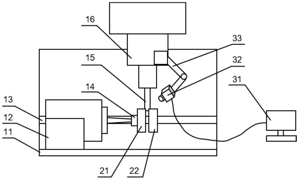
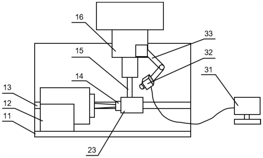
[0035] The invention as Figure 1-8 As shown, it includes a measurement platform and a test piece; the measurement platform includes an L-shaped substrate 11, a support rail 13, an exciter 12, a machine tool 16, a mandrel 15, a magnetic base 33, and an infrared thermal imager temperature measurement system;

[0036] The L-shaped base plate 11 includes a bottom plate and a vertical plate connected as one, the support rail 13 is horizontally arranged and fixedly connected to the vertical plate, the test piece is detachably connected to the support rail 13 through a bracket, and the test A force sensor 14 is fixedly connected on the part;

[0037] The vibrator 12 is fixedly connected to the base plate and is on one side of the support guide rail 13. The output...


PUM


Abstract

The invention discloses a tool deformation energy measuring device, and relates to the field of heat measuring equipment, in particular to the improvement of the tool deformation energy measuring device. The tool deformation energy measuring device is exquisite in structure, convenient to use and capable of effectively measuring and analyzing deformation of a tool. According to the technical scheme, the device comprises a measuring platform and a test piece; the measuring platform comprises an L-shaped substrate 11, a supporting guide rail 13, a vibration exciter 12, a machine tool 16, a core rod 15, a magnetic base 33 and a thermal infrared imager temperature measuring system. The measuring device has the beneficial effects that the condition that the tool deformation is one of reasons causing the temperature rise of the tool during cutting can be effectively verified; the heat source can be used as a research object to analyze the generation mechanism and rule of heat in thermal-mechanical coupling.

Description

technical field [0001] The invention relates to the field of heat measuring equipment, in particular to the improvement of a tool deformation energy measuring device. Background technique [0002] The problem of tool deformation and temperature rise has become a research hotspot in the field of aerospace manufacturing in recent years. In the metal cutting process, the force-thermal effect causes the deformation of the tool, which increases the wear of the tool, shortens the life of the tool, and seriously reduces the machining accuracy of precision parts. In order to study the force-heat effect of the cutting system and establish an accurate thermal-mechanical coupling error model, it is necessary to determine the source of heat generation. In the processing system, the bending and torsional potential energy of the tool is usually converted into heat in the form of friction or vibration, which causes the temperature of the tool to rise, resulting in machining errors. In th...

Claims


Application Information

Patent Timeline
IPC IPC(8): G01B21/32
CPCG01B21/32
Inventor 叶文华郭云霞徐祥梁睿君陈蔚芳
Owner NANJING UNIV OF AERONAUTICS & ASTRONAUTICS
Why Eureka
Try Eureka