A new energy vehicle water-cooled condenser

A new energy vehicle, water-cooled technology, applied in the direction of machines/engines, chemical instruments and methods, mechanical equipment, etc., can solve problems such as damage, dirt, and reduce heat transfer effects, so as to prevent excessive friction and avoid the formation of dirt , to avoid the effect of heat transfer effect

Active Publication Date: 2021-05-18
广州比美强机械技术开发有限公司
View PDF15 Cites 0 Cited by
  • Summary
  • Abstract
  • Description
  • Claims
  • Application Information

AI Technical Summary

Problems solved by technology

[0002] As the cooling device of new energy vehicles, the cold water condenser uses water as the heat dissipation medium to dissipate heat through water circulation. The refrigerant vapor enters the condenser from the upper part, and the heat is transferred to the water flowing in the pipe through the heat exchange tube. After being condensed, the refrigerant flows from the The bottom outlet pipe is discharged, and the heat transfer effect is good, but when the car is running, the gasoline smoke after combustion pollutes the water quality formed by cooling and condensation, making the water quality become hard water, resulting in the formation of dirt on the inner wall, reducing its The heat transfer effect makes the temperature of the cold water condenser continue to rise, causing damage to it, causing heat to easily accumulate in the cold water condenser

Method used


Image

  • A new energy vehicle water-cooled condenser
  • A new energy vehicle water-cooled condenser
  • A new energy vehicle water-cooled condenser

Examples


Embodiment 1

[0025] Such as Figure 1-Figure 6 Shown:

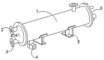
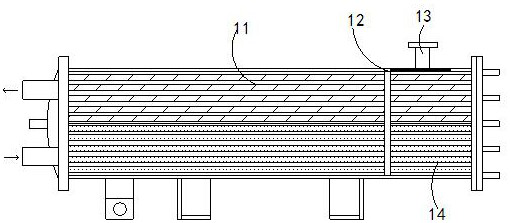
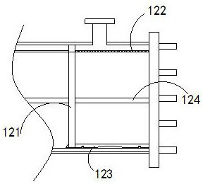
[0026] The present invention is a water-cooled condenser for a new energy vehicle, the structure of which includes a condensation mechanism 1, a water outlet 2, a water inlet 3, a smoke outlet pipe 4, a fixing frame 5, and a connecting shaft 6, and the water outlet 2 is installed on the condensation mechanism 1 On the left side of the condensing mechanism 1, the water inlet 3 is installed on the left side of the condensing mechanism 1, the smoke outlet pipe 4 is embedded in the lower end of the condensing mechanism 1, the fixing frame 5 is attached to the lower surface of the condensing mechanism 1, and the The connecting shaft 6 is embedded in the right end of the condensing mechanism 1. The condensing mechanism 1 is provided with a heat exchange pipe 11, a scraping mechanism 12, a smoke inlet pipe 13, and a condensation pipe 14. The right end of the scraping mechanism 12 is connected to the connecting shaft 6, the scraping mechanis...

Embodiment 2

[0034] Such as Figure 7-Figure 8 Shown:

[0035] Wherein, the sliding mechanism a4 is provided with a force receiving ring a41 and a force receiving mechanism a42, the force receiving ring a41 is attached to the surface of the force receiving mechanism a42, and the outer side of the force receiving ring a41 is attached to the surface of the drainage mechanism a1. Inside, the force receiving ring a41 is a triangular ring structure, located on the same central axis as the force receiving mechanism a42, so as to prevent the heat exchange tube 11 and the lower surface of the condenser tube 14 from being attached to the lower surface of the heat exchange tube 11 to cool and condense to form dirt, and to remove the dirt.

[0036] Wherein, the stressed ring a41 is provided with a stressed shaft b1, a compression plate b2, a gap plate b3, and a spring b4, the lower end of the stressed shaft b1 is embedded in the upper end of the spring b4, and the compressed plate b2 is attached to On...


PUM


Abstract

The invention discloses a water-cooled condenser for a new energy vehicle. The structure includes a condensation mechanism, a water outlet, a water inlet, a smoke outlet pipe, a fixing frame, and a connecting shaft. The condensation mechanism is provided with a heat exchange tube, a scraping mechanism, a smoke inlet Tubes and condensation pipes, through the compression force of heat, drive the gap mechanism to move to the left, and drive the expansion slot and the pleated plate to stretch, so that the gap between the expansion slots becomes larger, so as to achieve the effect of heat entering the interior from the gap of the expansion slot, preventing To affect the heat transfer effect, the sliding mechanism scrapes off the outer surface of the heat exchange tube and the condensation tube, so that the stressed ring can clean the water quality, scrape off the dirt attached to the outer surface of the heat exchange tube and the condensation tube, and prevent the The friction force between the force axis and the heat exchange tube and condensation tube is too large, so as to avoid the formation of dirt on the outer wall of the heat exchange tube and condensation tube, avoid reducing its heat transfer effect, prevent the accumulation of high temperature inside the cold water condenser, and avoid damage.

Description

technical field [0001] The invention relates to the field of new energy vehicles, in particular to a water-cooled condenser for new energy vehicles. Background technique [0002] As the cooling device of new energy vehicles, the cold water condenser uses water as the heat dissipation medium to dissipate heat through water circulation. The refrigerant vapor enters the condenser from the upper part, and the heat is transferred to the water flowing in the pipe through the heat exchange tube. After being condensed, the refrigerant flows from the The bottom outlet pipe is discharged, and the heat transfer effect is good, but when the car is running, the gasoline smoke after combustion pollutes the water quality formed by cooling and condensation, making the water quality become hard water, resulting in the formation of dirt on the inner wall, reducing its Due to the heat transfer effect, the temperature of the cold water condenser continues to rise, causing damage to it, causing ...

Claims


Application Information

Patent Timeline
Patent Type & Authority Patents(China)
IPC IPC(8): F01N3/04B08B9/023
CPCB08B9/023F01N3/0205F01N3/043F01N2240/22
Inventor 姚瑛
Owner 广州比美强机械技术开发有限公司
Why Eureka
Try Eureka