Dynamic projection system and dynamic projection method

A technology of dynamic projection and projection surface, applied in the fields of vehicle lighting, projection, and mechanical engineering

Active Publication Date: 2020-10-30
NINGBO SUNNY AUTOMOTIVE OPTECH
View PDF5 Cites 0 Cited by
  • Summary
  • Abstract
  • Description
  • Claims
  • Application Information

AI Technical Summary

Problems solved by technology

[0007] This application provides a dynamic projection system to solve or partially solve some problems in the prior art

Method used


Image

  • Dynamic projection system and dynamic projection method
  • Dynamic projection system and dynamic projection method
  • Dynamic projection system and dynamic projection method

Examples


Embodiment 1

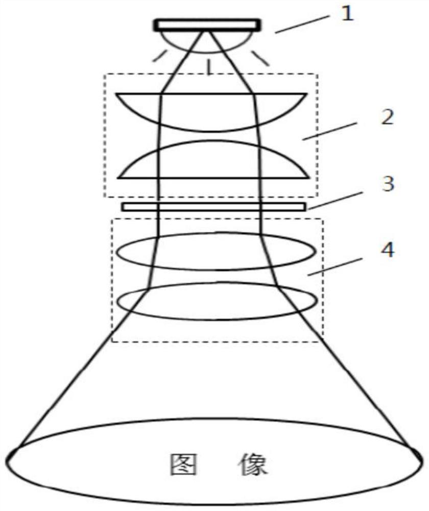
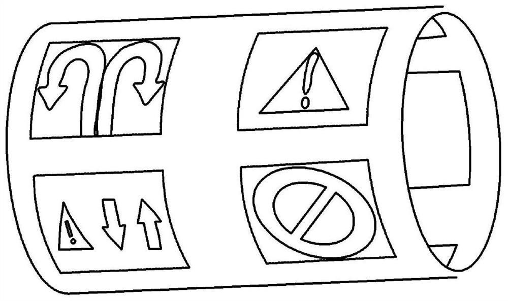
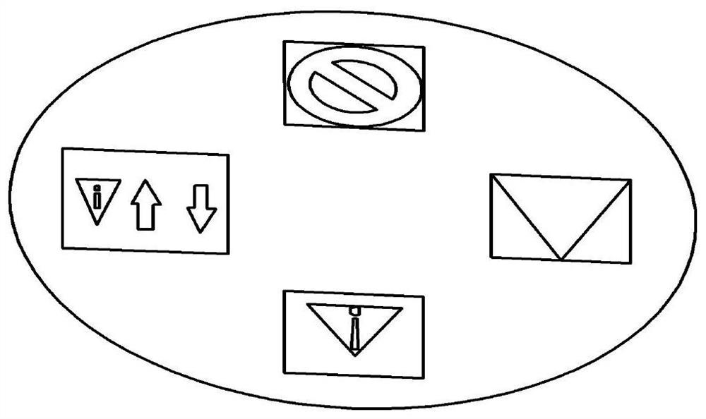
[0067] refer to image 3 and Figure 4 A dynamic projection system according to Embodiment 1 of the present application will be specifically described. in, image 3 A schematic structural diagram of a dynamic projection system 10 according to Embodiment 1 of the present application is shown. Figure 4 A schematic diagram showing the projection imaging effect of the dynamic projection system 10 according to Embodiment 1 of the present application.

[0068] Such as image 3 As shown in , in this embodiment, a dynamic projection system 10 includes an illumination module 1 , a cylindrical pattern module 2 , a projection module 3 , a mirror 4 and a drive module 5 .

[0069] The lighting module 1 includes a light source and one or more lenses (for example, two in the figure). The light source can be, for example, a high-brightness LED light source, and the one or more lenses include at least a collimating lens. The light source emits light beams for illumination, and the light ...

Embodiment 2

[0074] refer to Figure 5 and Figure 6 A dynamic projection system according to Embodiment 2 of the present application will be specifically described. in, Figure 5 A schematic structural diagram of a dynamic projection system 20 according to Embodiment 2 of the present application is shown. Figure 6 A schematic diagram showing the projection imaging effect of the dynamic projection system 20 according to Embodiment 2 of the present application.

[0075] Such as Figure 5 As shown in , in this embodiment, the dynamic projection system 20 includes an illumination module 1 , a plate pattern module 2 , a projection module 3 and a driving module 5 .

[0076] The lighting module 1 includes a light source and one or more lenses (for example, one in the figure). The light source can be, for example, a high-brightness LED light source, and the one or more lenses at least include a collimating lens. The light source emits light beams for illumination, and the light beams are firs...

Embodiment 3

[0081] refer to Figure 7 A dynamic projection system according to Embodiment 3 of the present application will be described in detail. image 3 A schematic structural diagram of a dynamic projection system 30 according to Embodiment 3 of the present application is shown.

[0082] Such as Figure 7 As shown in , in this embodiment, the dynamic projection system 30 includes an illumination module 1 , a plate pattern module 2 , a projection module 3 and a driving module 5 .

[0083] The lighting module 1 includes a light source and one or more lenses (for example, one in the figure). The light source can be, for example, a high-brightness LED light source, and the one or more lenses at least include a collimating lens. The light source emits light beams for illumination, and the light beams are first incident on a plurality of lenses including collimating lenses. As shown in the figure, in this example, one of the lenses shown may be a collimating lens for collimating a light...


PUM


Abstract

The invention discloses a dynamic projection system and a dynamic projection method. The dynamic projection system comprises an illumination module, a pattern module and a projection module, and is characterized in that the illumination module emits collimated light beams for illumination; a plurality of patterns are integrated on the pattern module, the pattern module can rotate or move so as toenable the collimated light beams from the illumination module to irradiate different patterns, and the collimated light beams carry corresponding pattern information after passing through the patternmodule; the projection module receives the collimated light beams carrying the corresponding pattern information and amplifies and projects the corresponding pattern information to a projection surface. According to the dynamic projection system, the structure tends to be miniaturized, the weight is light, and different image projections can be realized.

Description

technical field [0001] The present application relates to technical fields such as mechanical engineering, projection, and vehicle lighting, and more specifically, relates to a dynamic projection system and a dynamic projection method. Background technique [0002] With the development of automotive lighting technology, auxiliary lights are not limited to meet the needs of supplementary light, they can also be used to display the information of the car brand, and can project different logos at the corresponding distance in front of the car to play a role in people and cars. purpose of the interaction. [0003] For example, a pattern projection system emerging in the automotive industry in recent years has the function of lighting the floor and projecting the model or brand pattern of the car. It can project information such as the car logo on the ground. On the one hand, it can display the car brand On the other hand, it can play the role of lighting at night and reminding ...

Claims


Application Information

Patent Timeline
IPC IPC(8): G03B21/20
CPCG03B21/2066G03B21/206
Inventor 郎海涛张鹤腾杨佳桑鹏鹏
Owner NINGBO SUNNY AUTOMOTIVE OPTECH
Why Eureka
Try Eureka