Denoising method for high dynamic range laser focal spot image

A high dynamic range and image technology, applied in the field of image processing, can solve the problems of high noise and low accuracy of focal spot images, and achieve the effect of meeting accuracy requirements and improving accuracy

Pending Publication Date: 2020-10-30
XI'AN INST OF OPTICS & FINE MECHANICS - CHINESE ACAD OF SCI
View PDF0 Cites 0 Cited by
  • Summary
  • Abstract
  • Description
  • Claims
  • Application Information

AI Technical Summary

Problems solved by technology

[0005] In order to solve the problems of large noise and low accuracy in obtaining focal spot images by existing methods, the present invention provides a denoising method for high dynamic range laser focal spot images

Method used


Image

  • Denoising method for high dynamic range laser focal spot image
  • Denoising method for high dynamic range laser focal spot image
  • Denoising method for high dynamic range laser focal spot image

Examples


Embodiment

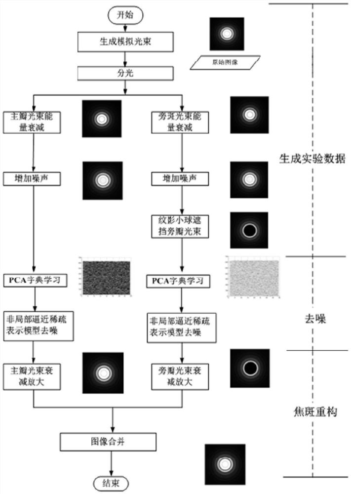
[0051] This embodiment introduces in detail the specific process of the denoising method for high dynamic range laser focal spot images according to an experimental process. For the process, see figure 1 :

[0052] 1. Simulate and generate the main lobe image and side lobe image with noise (generate experimental data)

[0053] 1.1. According to the principle of laser far-field focal spot intensity distribution, simulated beams are generated;

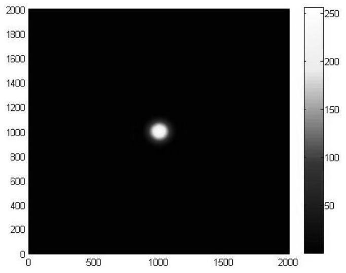
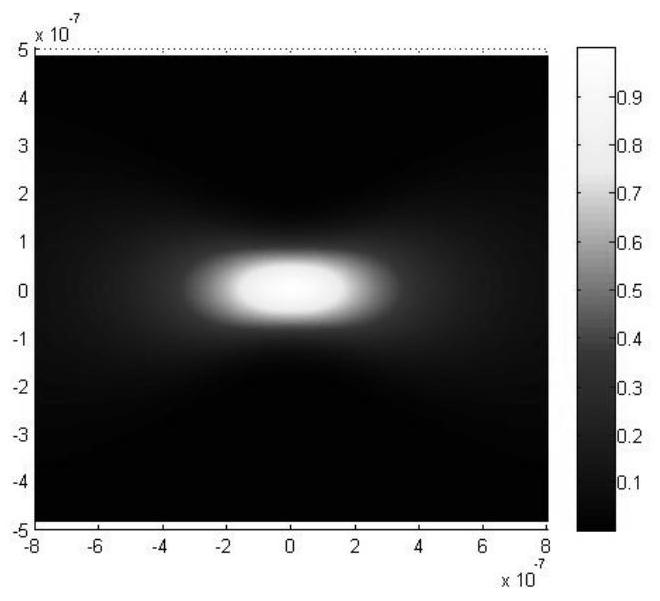
[0054] 1.2. According to the high dynamic range laser focal spot measurement mathematical model, the schlieren method simulates the generation of far-field main lobe images and side lobe images. It should be noted that: the main lobe images and side lobe images generated by simulation are all attenuated images In this embodiment, two beams of light are used for simulation, which are denoted as beam 1 and beam 2, as shown in Fig. 2(a), Fig. 2(b) and Fig. 3(a), Fig. 3(b). The embodiment specifically takes beam 2 as an example to explain ...


PUM


Abstract

The invention discloses a denoising method for a high-dynamic-range laser focal spot image, which improves the accuracy of restoring a main lobe image and a side lobe image of a high-dynamic-range far-field focal spot in a schlieren method and meets the accuracy requirement of high-dynamic-range laser focal spot measurement. The method comprises the following main steps: step 1, obtaining a main lobe image and a side lobe image with noise through analogue simulation; step 2, denoising processing is performed on the main lobe image; 3, denoising processing is carried out on the sidelobe image;and 4, fusing the noiseless main lobe image and the noiseless side lobe image to reconstruct an original focal spot image.

Description

technical field [0001] The invention belongs to image processing technology, and in particular relates to a method for denoising a high dynamic range laser focal spot image. Background technique [0002] In high-power solid-state laser devices, the distribution of laser far-field focal spots is an important indicator of beam far-field focusing, and it also indirectly reflects the wavefront status, which is directly related to whether the laser light speed can pass through the target hole smoothly. Therefore, the morphology distribution and energy concentration of the focal spot are obtained to select a suitable physical target, which provides a basis for improving the quality of the focal spot to meet the requirements of the physical target. [0003] The more commonly used method at present is to use the schlieren method to measure. In the process of measuring the laser far-field focal spot by the schlieren method, after the far-field focal spot is enlarged and imaged by th...

Claims


Application Information

Patent Timeline
IPC IPC(8): G06T5/00G06K9/62
CPCG06F18/2135G06F18/23213G06T5/70
Inventor 谭萌王拯洲王力李刚弋东驰魏际同
Owner XI'AN INST OF OPTICS & FINE MECHANICS - CHINESE ACAD OF SCI
Why Eureka
Try Eureka