Coil structure, coil parameter determination method, device and electronic equipment

A technology of coil turns and coils, applied in the field of magneto-optical trap systems and storage media, can solve problems such as obstacles, optical window space limitations, and increased size of anti-Helmholtz coils, so as to avoid the influence of magnetic field gradients and ensure Magnetic field gradient, effect of reducing influence

Active Publication Date: 2021-08-13
UNIV OF SCI & TECH OF CHINA
View PDF10 Cites 0 Cited by
  • Summary
  • Abstract
  • Description
  • Claims
  • Application Information

AI Technical Summary

Problems solved by technology

[0004] However, there are at least the following problems in the prior art: First, the anti-Helmholtz coil is easy to block the beam path, which leads to the poor state of the trapped atomic groups or the limitation of the subsequent optical window space, thus hindering the use of cold atoms. Second, as the volume of the transparent cavity increases, the size of the anti-Helmholtz coil will also increase
The increase in the size of the anti-Helmholtz coil will affect the magnetic field gradient provided by the magnetic field operating point

Method used


Image

  • Coil structure, coil parameter determination method, device and electronic equipment
  • Coil structure, coil parameter determination method, device and electronic equipment
  • Coil structure, coil parameter determination method, device and electronic equipment

Examples


Embodiment Construction

[0055] The present disclosure will be further described in detail below in conjunction with the accompanying drawings and embodiments. It can be understood that the specific embodiments described here are only for explaining the present disclosure, rather than limiting the present disclosure, and various features recorded in the embodiments can be combined to form multiple optional solutions. In addition, it should be noted that, for the convenience of description, only some structures related to the present disclosure are shown in the drawings but not all structures.

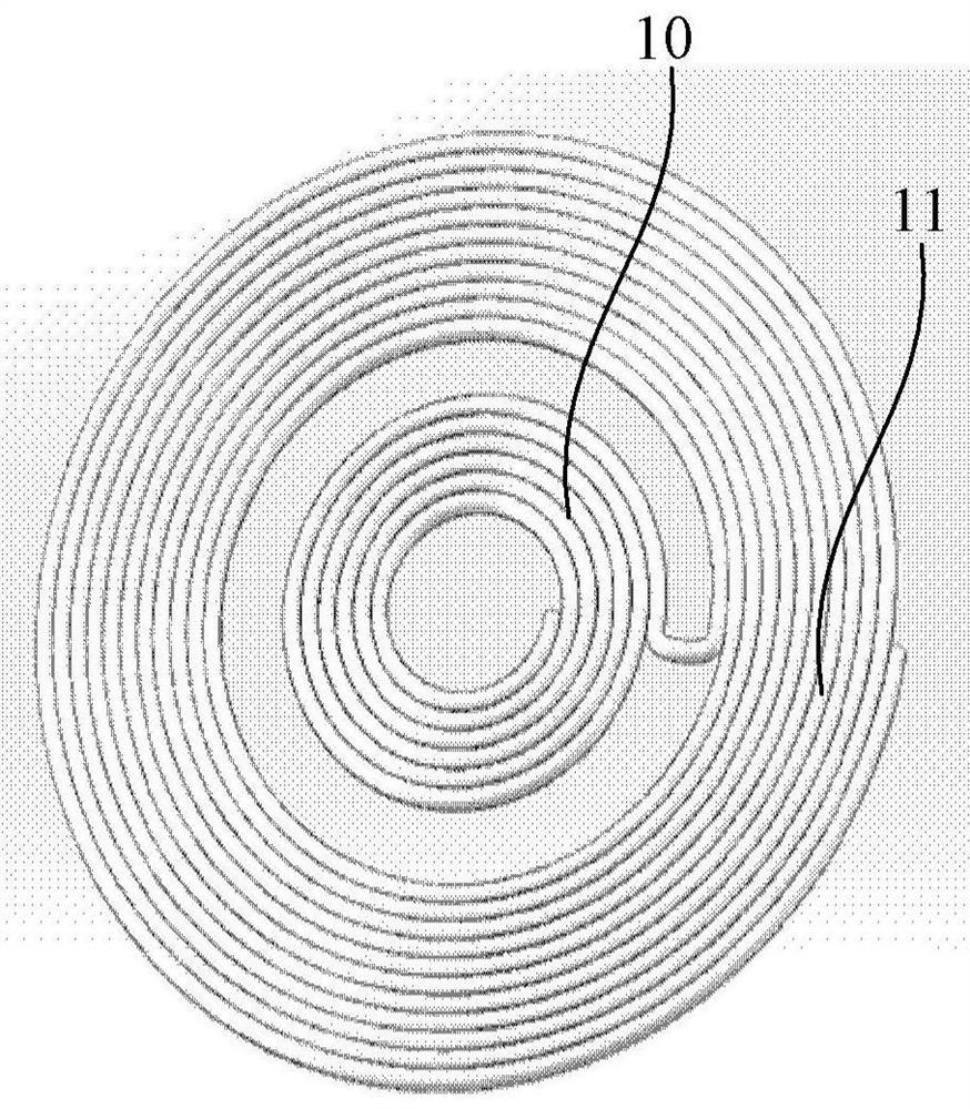
[0056] The anti-Helmholtz coil is a three-dimensional structure whose volume cannot be ignored. At the same time, the magnetic field working point of the anti-Helmholtz coil is at its geometric center. During use, it needs to be placed through the cavity of the vacuum device to meet the working conditions of the magnetic field working point. The working conditions include the absolute The value is zero, and th...


PUM


Abstract

The embodiment of the disclosure discloses a coil structure, a coil parameter determination method, device, electronic equipment, system and storage medium. Including: the inner coil and the outer coil located on the same plane, the inner coil and the outer coil are circular coils formed by coiling the wires; the inner coil and the outer coil are connected in a way to generate the direction of the axial magnetic field in the opposite direction; when the inner coil After the current is passed through the outer coil, the three-dimensional magnetic field of the magneto-optical trap will be generated. In the embodiment of the present disclosure, since the coil structure is a planar structure, when in use, it can be placed in parallel near a plane of the cavity wall of the cavity to realize the magnetic field operating point required for providing the magneto-optical trap without causing damage to the coil. Obstruction of the beam path on other cavity wall planes. Since it can be placed near a cavity wall plane of the cavity, the magnetic field operating point required by the magneto-optical trap can be provided. Therefore, the size of the coil structure has nothing to do with the volume of the cavity, and the influence of the magnetic field gradient provided by the magnetic field operating point is avoided. influences.

Description

technical field [0001] The embodiment of the present disclosure relates to the technical field of atomic cooling, and in particular relates to a coil structure, a coil parameter determination method, a device, an electronic device, a magneto-optical trap system, and a storage medium. Background technique [0002] Magneto-optical trap is the most widely used first-level cooling method for trapping neutral atoms. It has the advantages of easy construction and stable properties. The working principle is as follows: for an isolated second-level atom in one dimension, assuming Level triple degeneracy, the lower energy level has no degeneracy, and there is a linearly changing magnetic field in space, then at the position near the zero point of the magnetic field, due to the Zeeman effect, the energy level will move with the magnitude of the magnetic field, and emit from both sides of the zero point to the zero point The red detuned circularly polarized light will make its resonanc...

Claims


Application Information

Patent Timeline
Patent Type & Authority Patents(China)
IPC IPC(8): H01F7/20G21K1/00
CPCG21K1/006H01F7/20
Inventor 陈梁邹长铃卢征天董春华郭光灿
Owner UNIV OF SCI & TECH OF CHINA
Why Eureka
Try Eureka