
Groove cutting device for shipbuilding steel plate

A technology for bevel cutting and shipbuilding steel plates, applied in auxiliary devices, welding/cutting auxiliary equipment, manufacturing tools, etc., can solve the problems of low practicability, shifting of steel plates, no limit measures for steel plates, etc., and achieve the effect of ensuring alignment and positioning , Guarantee the integrity and improve the effect of practicability

Inactive Publication Date: 2021-05-28
吴相彩
View PDF1 Cites 0 Cited by
  • Summary
  • Abstract
  • Description
  • Claims
  • Application Information

AI Technical Summary

Problems solved by technology

[0005] First, there is no limit measure when the steel plate is cut in this technical solution, which will easily cause the situation that the steel plate will always be displaced during the cutting process;
[0006] Second, the cutting machine in this technical solution has no limit measures, and it is impossible to quickly determine whether the cutting edge of the steel plate is in alignment with the cutting mechanism, and the practicability is low

Method used

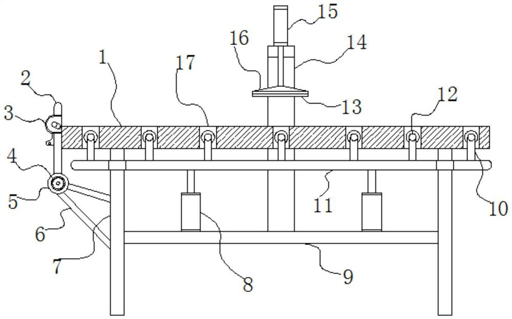

Image

  • Groove cutting device for shipbuilding steel plate
  • Groove cutting device for shipbuilding steel plate
  • Groove cutting device for shipbuilding steel plate

Examples


Embodiment Construction

[0026] In order to make the technical means, creative features, goals and effects achieved by the present invention easy to understand, the present invention will be further described below in conjunction with specific embodiments.

[0027] In describing the present invention, it should be understood that the terms "upper", "lower", "front", "rear", "left", "right", "top", "bottom", "inner", " The orientation or positional relationship indicated by "outside", etc. is based on the orientation or positional relationship shown in the drawings, and is only for the convenience of describing the present invention and simplifying the description, rather than indicating or implying that the referred device or element must have a specific orientation, so as to Specific orientation configuration and operation, therefore can not be construed as limiting the present invention; in the description of the present invention, it should be noted that, unless otherwise clearly specified and limit...


PUM


Abstract

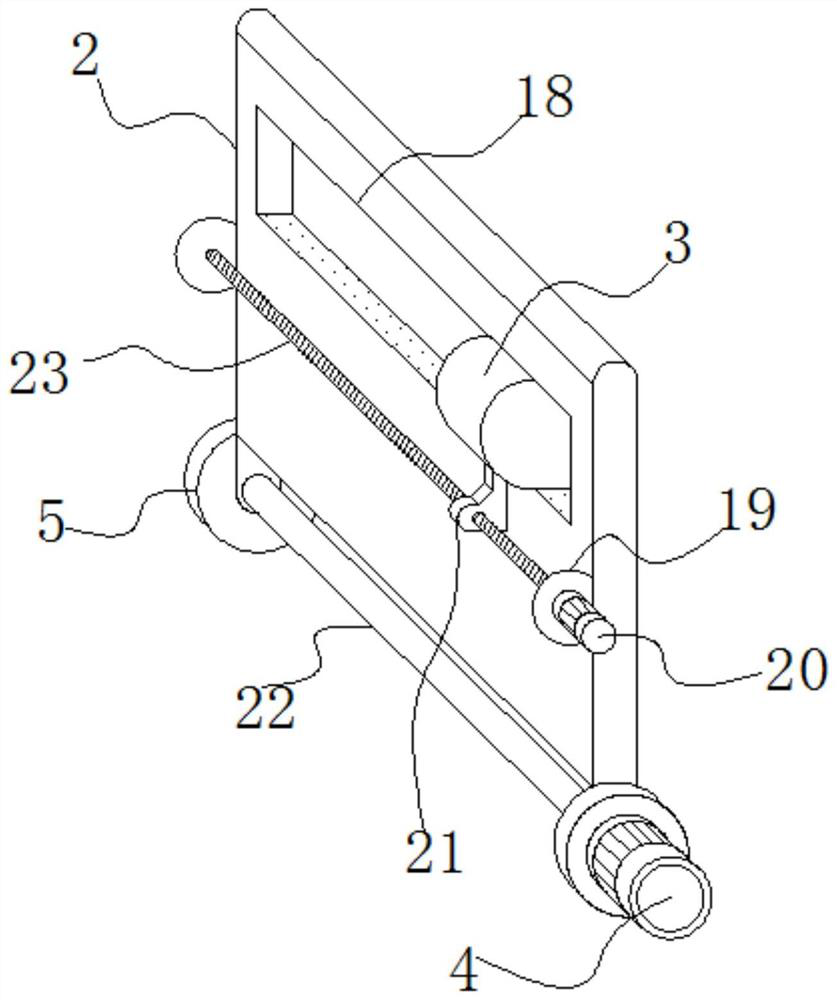
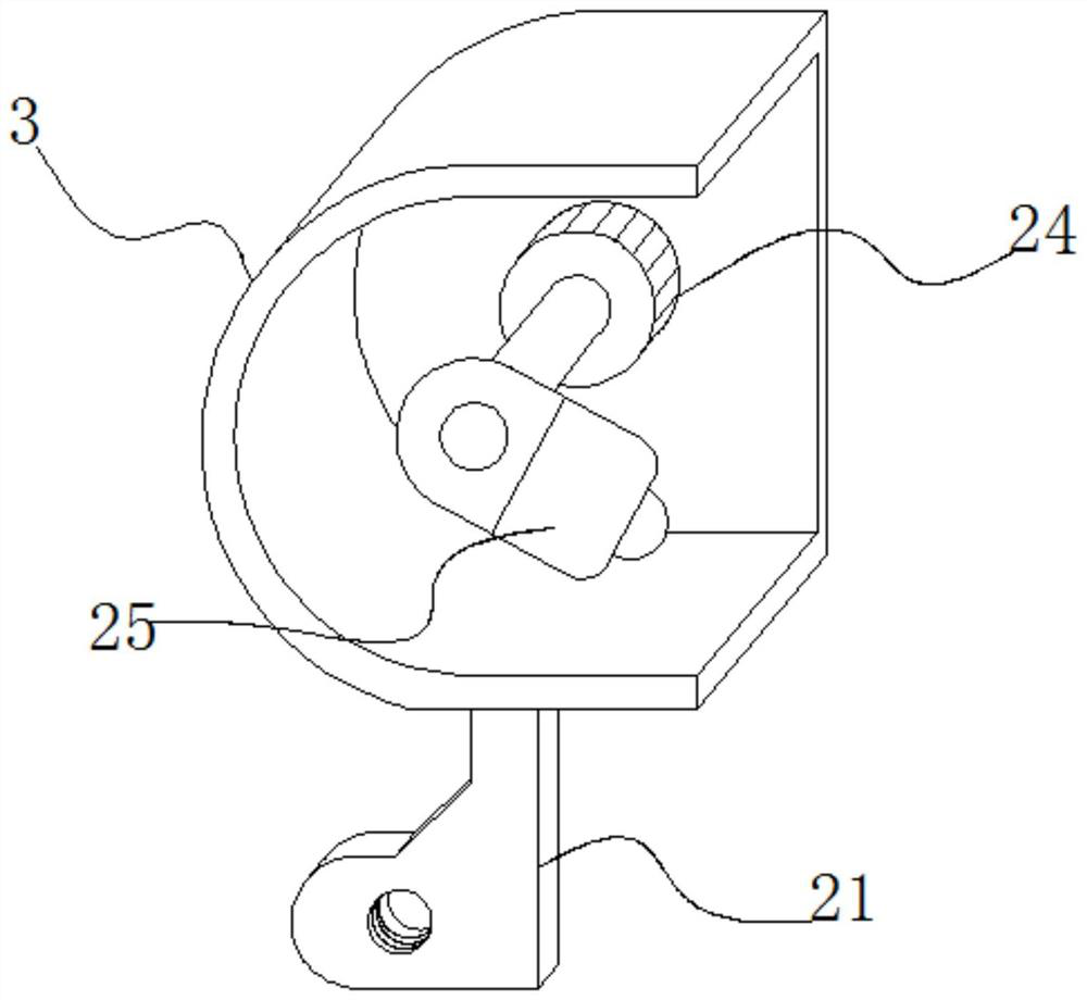
The invention relates to the technical field of shipbuilding steel plate machining, and discloses a groove cutting device for a shipbuilding steel plate. The groove cutting device comprises a machine table, wherein supporting plates are fixedly connected to the left side and the right side of the bottom of the machine table in a vertically downward mode, a bearing plate is fixedly connected between the two supporting plates, jacking cylinders are fixedly mounted on the left side and the right side of the upper portion of the bearing plate in a vertically upward mode, the upper ends of piston rods of the jacking cylinders are fixedly connected with the same bearing platform, and a plurality of jacking rods distributed at equal intervals are fixedly connected to the upper portion of the bearing platform in a vertically upward mode. According to the device, the two jacking cylinders operate to drive the bearing platform to increase the height so as to guarantee that multiple guide rollers on the bearing platform stretch out of a rectangular through opening of the machine table, the steel plate can be flexibly guided and moved under the action of the guide rollers until the left side of the steel plate is attached to the right side face of a limiting baffle on the left side of the machine table, and the alignment locating effect of the steel plate is guaranteed.

Description

technical field [0001] The invention relates to the technical field of shipbuilding steel plate processing, in particular to a bevel cutting device for shipbuilding steel plate. Background technique [0002] At present, due to the harsh working environment of the ship, the hull shell is subject to chemical corrosion, electrochemical corrosion, marine organisms, and microbial corrosion of seawater; the hull is subjected to large wind and wave impacts and alternating loads; the shape of the ship makes the processing method complex and other factors, Therefore, there are strict requirements on steel for hull structure. First of all, good toughness is the most critical requirement. In addition, high strength, good corrosion resistance, welding performance, processing and forming performance and surface quality are required. [0003] The retrieved publication number CN 210549083 U discloses a bevel cutting device for shipbuilding steel plates, including a cutting platform, the c...

Claims


Application Information

Patent Timeline
IPC IPC(8): B23K7/00B23K7/10B23K37/04B23K37/02
CPCB23K7/002B23K7/10B23K37/0252B23K37/0435
Inventor 吴相彩
Owner 吴相彩
Learn More