Universal tool for replacing insulator

A general-purpose tool and insulator technology, applied in the direction of overhead lines/cable equipment, etc., can solve the problems of many limiting factors, undiscovered patent publications, and complicated operation.

Active Publication Date: 2020-10-30
TIANJIN ELECTRIC POWER TRANSMISSION & TRANSFORMATION ENG CORP +2
View PDF8 Cites 0 Cited by
  • Summary
  • Abstract
  • Description
  • Claims
  • Application Information

AI Technical Summary

Problems solved by technology

[0002] It is very common to replace insulators in the work of overhead transmission lines. In the past, the processing method was to use a single-piece fixture or a bottle holder. When using a single-piece fixture, the specification and model of the insulator and the bowl head need to be confirmed on site first. Whether there is a ring-shaped protruding clamp at the end, and then select the single-piece clamp of the corresponding specification and model. It can only be used when the specification model, the ring-shaped protruding clamp, and the single-chip clamp of the corresponding specification and model are satisfied at the same time; When using the bottle holder, because the structure of the bottle holder is extremely long, it needs to be transported by a large vehicle, and at the same time, it needs to use an inverted chain as a force-bearing structure to cooperate with it. The operation is cumbersome and the work efficiency is extremely low.
[0003] When performing short-cut operations, the power grid regulators consider the importance of power supply lines, and the power outage time is relatively short, while the operation of replacing insulators uses wires as the main force-bearing components, which is difficult and takes a long time. Traditional tools There are too many limiting factors in use, which makes it difficult to complete the work safely within a limited time. Therefore, the development of a general tool for replacing insulators is of great significance
[0004] Through the search, no patent publications related to the patent application of the present invention have been found

Method used


Image

  • Universal tool for replacing insulator
  • Universal tool for replacing insulator
  • Universal tool for replacing insulator

Examples


Embodiment Construction

[0043] The present invention will be described in further detail below in conjunction with specific examples. The following examples are only descriptive, not restrictive, and cannot limit the protection scope of the present invention.

[0044] The raw materials used in the present invention, unless otherwise specified, are conventional commercially available products; the methods used in the present invention, unless otherwise specified, are conventional methods in the art.

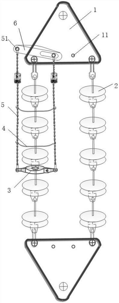
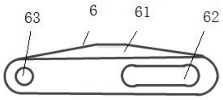
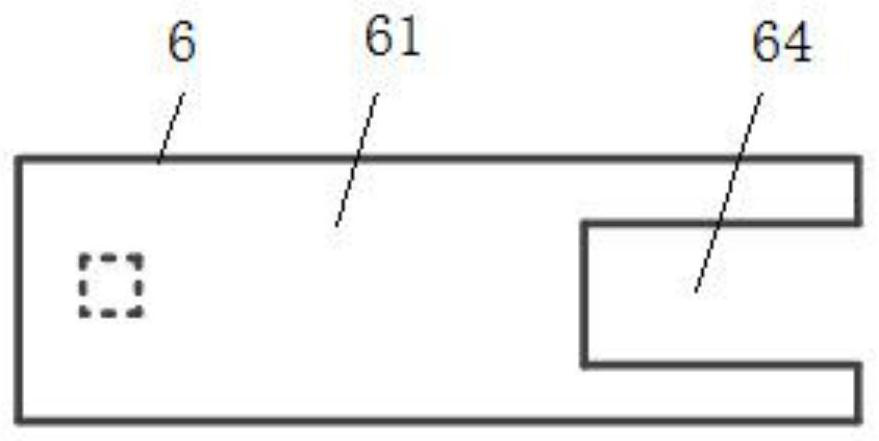
[0045] A universal tool for replacing insulators, such as figure 1 As shown, the tool includes a bowl head end fixture 3, a bottle dragging belt 4, a force-reversed chain 5 and a triangular plate fixture 6, and a plurality of insulators 2 are fixed between the two triangular plates 1, and the plurality of insulators can be used in turn. Detachable and connected, the triangular plate clamp can be detachably connected with the triangular plate, and the triangular plate clamp can also be detachably connecte...


PUM


Abstract

The invention relates to a universal tool for replacing an insulator. The tool comprises a socket end fixture, a bottle dragging belt, a stress chain block and a triangular plate fixture, the triangular plate fixture can be detachably connected with a triangular plate; the triangular plate fixture can be detachably connected with the stressed chain block; the stressed chain block can also be detachably connected with the socket end fixture and the bottle dragging belt, the socket end fixture can clamp and release an insulator, the bottle dragging belt can support the insulator arranged above the bottle dragging belt, and the triangular plate fixture, the stressed chain block and the socket end fixture can be matched to loosen the insulator fixedly arranged between two triangular plates. According to the universal tool, the safety in the transferring process is improved, transportation of large vehicles is not needed, the transportation cost is reduced, the problem that the insulator cannot be replaced due to the fact that large tools cannot be transported under road conditions is solved, universal clamps at the two ends are convenient to install in the using process, and the working efficiency is greatly improved.

Description

technical field [0001] The invention relates to the technical field of power line construction and maintenance equipment, in particular to a general tool for replacing insulators. Background technique [0002] It is very common to replace insulators in the work of overhead transmission lines. In the past, the processing method was to use a single-piece fixture or a bottle holder. When using a single-piece fixture, the specification and model of the insulator and the bowl head need to be confirmed on site first. Whether there is a ring-shaped protruding clamp at the end, and then select the single-piece clamp of the corresponding specification and model. It can only be used when the specification model, the ring-shaped protruding clamp, and the single-chip clamp of the corresponding specification and model are satisfied at the same time; When using the bottle holder, because the structure of the bottle holder is extremely long, it needs to be transported by a large vehicle, a...

Claims


Application Information

Patent Timeline
Patent Type & Authority Applications(China)
IPC IPC(8): H02G1/02
CPCH02G1/02
Inventor 朱春雷殷子沛王丹海田宇宸曹正张宇超王德祥
Owner TIANJIN ELECTRIC POWER TRANSMISSION & TRANSFORMATION ENG CORP
Why Eureka
Try Eureka