[0023] The technical solutions in the embodiments of the present invention will be clearly and completely described below in conjunction with the accompanying drawings in the embodiments of the present invention. Obviously, the described embodiments are only a part of the embodiments of the present invention, rather than all the embodiments. Based on the embodiments of the present invention, all other embodiments obtained by those of ordinary skill in the art without creative work shall fall within the protection scope of the present invention.
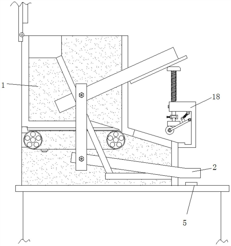
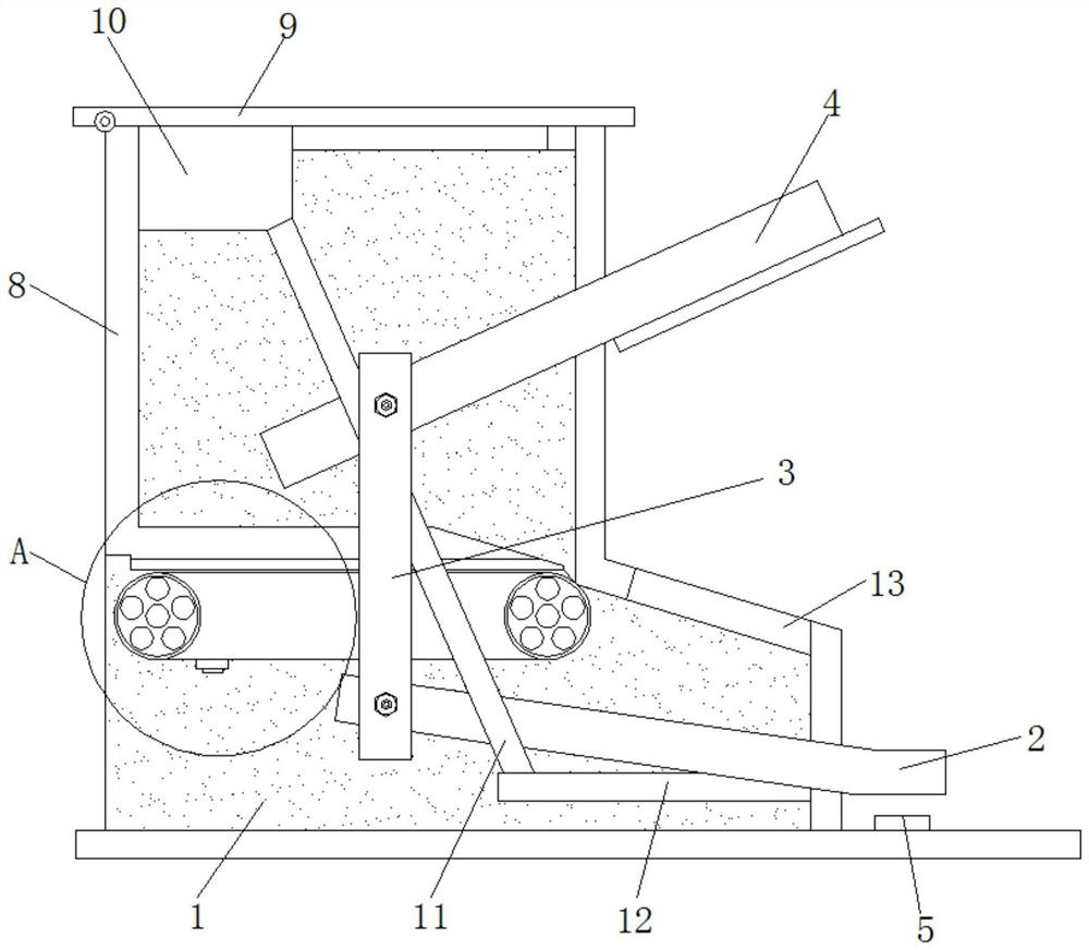
[0024] See Figure 1-4 , A continuous take-out device for business management brochures, comprising a housing 1, a first pressure plate 2 is movably connected to the inside of the housing 1, and a first connecting rod 3 is movably connected to one end of the first pressure plate 2 and the first connecting rod 3 The top end is movably connected to the second pressure plate 4, one end of the first pressure plate 2 is provided with a push switch 5, the inner rotation of the housing 1 is connected with a runner 6, and the push switch 5 is electrically connected with the single-phase motor to make the push switch 5 The rotation of the runner 6 can be controlled by controlling the rotation of the motor. The outer side of the runner 6 is connected with a push block 7, the outer side of the runner 6 is connected with a belt, the belt is connected with the push block 7, and the runner 6 is connected with the motor Transmission connection, therefore, the motor can drive the runner 6 to rotate, the belt can drive the push block 7 to rotate, the upper side of the runner 6 is provided with a connecting plate 8, and the surface of the connecting plate 8 is provided with a sliding groove, and the sliding groove slides with the push block 7 Connected so that the push block 7 can push out the brochure from the connecting plate 8. The top of the housing 1 is rotatably connected with a cover plate 9, the inner wall of the housing 1 is provided with a first fixing plate 10, and one end of the first fixing plate 10 is fixedly connected with a Two connecting rods 11, the second connecting rod 11 is movably connected with the second pressing plate 4, and the first pressing plate 2 is movably connected with the second fixing plate 12, so the second connecting rod 11 and the second fixing plate 12 function as a limiter , The bottom end of the second connecting rod 11 is fixedly connected with a second fixing plate 12, the outer side of the housing 1 is provided with a take-out port 13, and the surface of the second pressing plate 4 is movably connected with a first connecting shaft 14 and a first connecting shaft 14 A spring is sleeved on the outer side, and the spring plays the role of driving the first connecting shaft 14 back to the initial position. The bottom end of the first connecting shaft 14 is movably connected with a pressure block 15, and the outer side of the pressure block 15 is movably connected with a rotating shaft 16. The inside of the rotating shaft 16 is rotatably connected with a third link 17, one end of the third link 17 is rotatably connected with a fixing member 18, the middle of the third link 17 is fixedly installed with a spring, the fixing member 18 is fixedly connected with the housing 1, and the spring starts To the role of the connection.
[0025] Working principle: When using, first open the cover 9, put the brochure through the limit of the connecting plate 8, place the brochure on the bottom of the connecting plate 8, manually press the first pressure plate 2 to make the first pressure plate 2 clockwise downward Rotate, the first connecting rod 3 is driven by the first pressing plate 2 to rotate upwards, the first connecting rod 3 drives the second pressing plate 4 to rotate upwards counterclockwise, the first pressing plate 2 rotates downwards to contact the push switch 5, press the switch 5 Through the single-phase electrical connection with the motor, the motor drives the runner 6 to rotate clockwise, the runner 6 makes the belt rotate clockwise, and drives the push block 7 on the outside of the belt to push the lowest end of the sliding groove from the left side of the chute set on the connecting plate 8. The brochure moves to the right. The outer side of the runner 6 is connected with a belt, and the belt is connected with the push block 7 so that the brochure is pushed out to the take-out port 13. The second pressing plate 4 rotates upwards and contacts the second connecting rod 11. The first pressing plate 2 rotates and contacts the second fixing plate 12, and the second connecting rod 11 and the second fixing plate 12 play a role of limiting the position. Remove the brochure from the take-out port 13, so that the first pressing plate 2 rotates upward and leaves the press Switch 5, the motor stops rotating, and the second pressing plate 4 rotates clockwise downwards, so that the first connecting shaft 14 slides down, the spring is compressed, and the first connecting shaft 14 drives the pressing block 15 to move downward, causing the rotating shaft 16 to move downward , The press block 15 fixes the slide out brochure, people first press the first press plate 2 to lift the second press plate 4, take the first brochure fixed by the press block 15, and then press the switch 5 to connect , Make the second book easy to slide out, easy to take next time, solve the problem of messy storage, easy to organize, wind and rain.
[0026] In summary, the continuous take-out device for the corporate management brochure realizes the continuous access to the brochure through the connection of the housing 1, the first pressing plate 2, the first connecting rod 3, the second pressing plate 4, and the runner 6. Taking it out solves the problem that the existing technology is to pile up the business management brochures on the table but the storage is relatively messy, easy to organize, so that people can understand in advance when conducting consulting services.
[0027] The continuous retrieval device of the corporate management brochure realizes the fixation of the brochure when it is taken out through the connection of the first fixing plate 10, the second connecting rod 11, the second fixing plate 12, and the third connecting rod 17. The existing technology is the problem of stacking corporate management brochures on the table, which is easy to fall, windproof and rainproof, and can be placed outdoors. It not only achieves the purpose of publicity, but also enables employees to efficiently understand and accept the management methods and management methods of the company. content.
[0028] Although the embodiments of the present invention have been shown and described, those of ordinary skill in the art can understand that various changes, modifications, and substitutions can be made to these embodiments without departing from the principle and spirit of the present invention. And variations, the scope of the present invention is defined by the appended claims and their equivalents.